
The mechanical seal was invented in the 1940s as a replacement for packings. The device needed to fit in the same cavity (i.e. the stuffing box) as the packing because of volume limitations. Advantages over packings included reduced wear against the pump shaft and elimination of the need to periodically tighten the packing nut to keep it tight against the shaft. Mechanical seals were more expensive, so the purchase cost had to be offset by low maintenance costs and increased life expectancy of the seal. Fast forward 75 years, and it is clear the mechanical seal has successfully met these challenges. As a result, mechanical seal design has not changed very much. One could argue that the basic design has not changed at all. The device is still basically two faces in sliding rotation relative to each other. They must be smooth, optically flat, and in parallel and close to one another. That last feature is where the "rub" comes in. Ring smoothness and flatness can be routinely accomplished in manufacturing. The parallel/proximity is determined by many factors including the seal assembly, the environment in which it operates and the size constraints of the stuffing box. Every seal application poses a different set of these circumstances to the rotating rings. Careful engineering is directed at the operating environment of sealed fluid, temperature, pressure, pump speed, seal configuration, seal ring material and its running surface characteristics. Balancing these competing parameters is essential to achieve the parallel/close proximity required for proper seal operation and wear life. Leakage is proportional to the proximity of the ring faces. If they remain parallel, a well-behaved hydrodynamic lubricating film will form between them with minimal leakage. Figure 1 shows a simple diagram of a single seal arrangement with a rotating primary ring. This seal is at rest—there is no fluid pressure nor rotation. In this state, the seal rings are parallel with and in proximity to each other; they are touching. When the seal is pressurized, the primary ring will deform under the pressure.
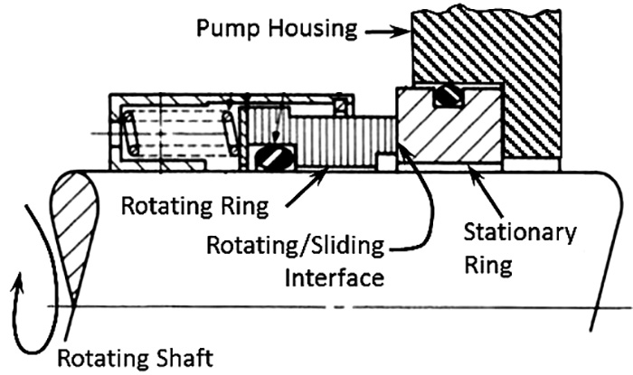 Figure 1. A diagram of a single mechanical seal at rest (Graphics courtesy of Carbide Derivative Technologies Inc.)
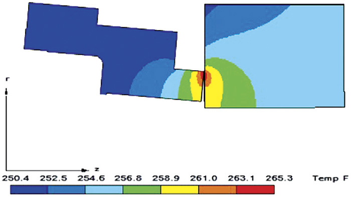 Figure 2. Mechanical seal rings in operation with induced deformations from pressure and temperature