

Vibration problems in vertical pumps can be challenging to diagnose and resolve. Not only are the long, cantilevered column and bowl assemblies more susceptible to resonant excitation than their horizontal pump brethren, but available vibration data is usually limited to aboveground locations. A United States West Coast water authority experienced this challenge when eight vertical pumps at one of their intake facilities exhibited persistent vibration accompanied by excessive noise. The pumps had been problematic since installation and had undergone warranty repairs, field testing and unsuccessful attempts at remediation.
After the installation of what was thought to be a solution caused the vibration problems to worsen, the water authority approached an independent, aftermarket-focused pump rebuilder to perform a comprehensive engineering study. This study required additional testing of the pumps, development and verification of analytical models and an in-depth forensic inspection.
When the study concluded, the aftermarket company was able to successfully identify the root cause of the problems: a combination of excessive component tolerances and incorrect assumptions made during the original vibration study. With this knowledge in hand, they developed and implemented the changes necessary to ensure reliable operation. The successful diagnosis and resolution of the problem was made possible by the aftermarket company’s capability to perform all steps of the process in-house, including data collection, engineering analysis and upgrade development, implementation of the solution and post-installation field testing.
Background
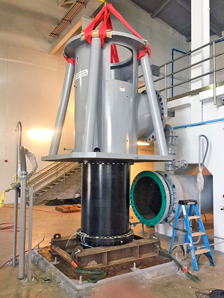
The water authority installed and commissioned eight large three-stage vertical intake pumps that were driven by 2,000 horsepower (hp) motors using a variable frequency drive (VFD). The procurement document required a ±20% separation range between the first mode of any natural frequencies and the pumps’ desired operating speeds. However, vibration amplitudes present from the onset of pump operation suggested that a resonant condition was within the excitation range. The pumps also exhibited a grinding noise during operation.
While still under warranty, the pumps were sent back to the OEM for repair to try to diagnose the grinding noise. Inspection data from that time found quality issues in the original manufacturing that were addressed; however, when the refurbished pump was returned to operation, both the noise and the vibration persisted. To diagnose the problem, the water authority commissioned a vibration study through an engineering firm. This study identified the first bending mode at 660 cycles per minute (cpm) (within a ±5% band) for both the aboveground discharge head/motor assembly and the belowground column/bowl assembly.
Based on their findings, the engineering firm recommended that braces be installed on the lower flange of the second column. It is not uncommon for a quick fix to be introduced through reinforcement without proper analysis being completed. Engineers implementing these solutions believe that reinforcement will resolve the resonant frequency, but instead they shift the critical frequency from one mode to another. This frequency shift might not only render the solution ineffective, but it could also make vibration worse or further constrain the operating speed range.
Unfortunately, the solution provided was not successful and the newly recommissioned pump failed with only 700 hours of runtime. With the pump out of warranty, the water authority brought in an independent, aftermarket-focused pump company to help them troubleshoot the problem.
Something Does Not Add Up
The first potential problem that the aftermarket pump company identified was the relative lack of data available to support the first study diagnosis and solution. The engineering firm that conducted the first study used a set of nine accelerometers attached to each pump, with the lowest set at 300 inches below the pump base and the highest set at the top of the motor. While this provided better data than only looking at aboveground information, it did not take enough data points to provide a high-resolution picture of the stationary assembly motion.
Another red flag was the coincidence of the first bending mode resonant frequency on the aboveground and belowground assemblies. If the structures below and above the pump base had been identical, this result might have been accepted. However, these assemblies are different structurally, making it virtually impossible for these two structures to have the same natural frequencies. Additionally, the response of the structures on the measurement channels were phased relative to each other; the motion of the motor assembly was out-of-phase with respect to the column assembly by about 180 degrees at 300 inches below the base.
With these questions in mind, the aftermarket pump company and water authority decided to undertake a new series of tests to accumulate more data and get a clearer picture of how the pump behaved during different operating modes.
In-Depth Testing Provides Answers
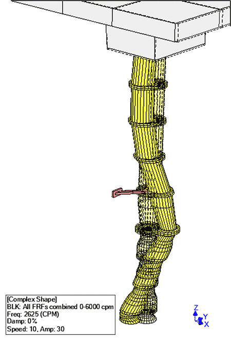
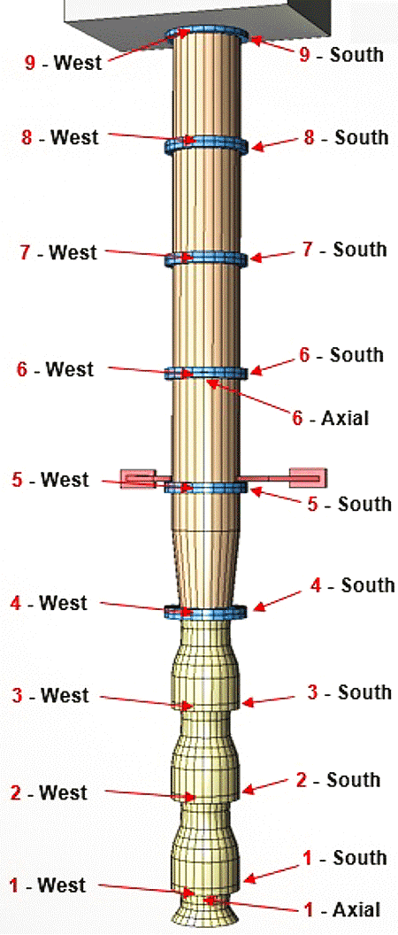
A test plan was developed to measure, analyze, characterize and compare noise and vibration on four of the machines. This plan included the use of 80 submersible accelerometers with integral cables, with 20 sensors installed on each pump. Additionally, nine triaxial sensors were used aboveground on the motor and discharge piping. Vibration and microphone data were collected continuously using two 24-channel online monitoring systems. Motion amplification video was also taken throughout the process. Data was collected for each pump including run-up, steady state operation, varying operating conditions and coast-down. An operational deflection shape study (ODS) of each pump and motor was performed, while operating pumps both independently and in various combinations.
In addition to data taken while the pumps were running, a modal analysis survey of each pump and motor was completed with the intake empty and the pumps nonoperational.
The test data showed that the belowground assembly behaved different from the engineering firm’s assessment. Instead of moving the natural frequency up above the maximum running speed to 1,000 cpm as predicted, the first bending mode with the brace installed was determined to be at 300 cpm. This was below the first bending mode frequency posited by the original engineering firm.
Concerned by the test data, the aftermarket pump company proceeded to develop a 3D model and finite element analysis (FEA) discovery study to better understand the conclusions. While the original engineering firm had used a 3D structural FEA model from a similar pump and scaled it to the approximate size of the pumps in question, the new study undertaken by the aftermarket pump company created a new model of the actual pumps in question. This model was verified against the actual field test results to ensure model accuracy and allow the team to confidently use the model to predict behaviors in the virtual model environment.
Because of the questions arising from the original study’s results, the braces were removed from the verified model to predict what the original frequencies would have been without this reinforcement. This step was undertaken to confirm the original findings of the identical frequencies for the first bending mode on the aboveground and belowground structures. Removing the braces predicted that the first bending mode of the belowground column structure was not 660 cpm, but 126 cpm. This is in contradiction to the original study’s findings, made sense when considering the natural frequency of the reinforced structure at 300 cpm.
Further analysis provided illumination on how the original data had been misinterpreted. While the first bending mode of the aboveground assembly was verified at around 660 cpm, it was the second bending mode of the belowground assembly that was within ±5% of 660 cpm with the motion out-of-phase to the aboveground assembly by 180 degrees. With this information, the aftermarket pump company was able to reconstruct the original phenomena that caused the resonance-driven high vibration, component wear and grinding noise. Because the original testing was only done with nine accelerometers, the shape of the excited mode was not reliably discerned. Because the original study assumed the incorrect resonant mode, it did not accurately predict how the reinforcement would affect the belowground assembly.
Next Steps
With the problem correctly identified, an action plan could be developed to modify the pump in a way that allowed operation within the desired speed range without exciting any resonant modes. The approved plan included stiffening and loosening various components in a way that provided margin separation from all resonant modes. Tolerances and alignment were improved to preclude contact and premature wear of rotating and stationary pump components.
To successfully shift the resonant modes out of the operating speed range, changes were made to both the aboveground and belowground reinforcements. The discharge head was modified to eliminate the four reinforcing 6-inch pipe braces, which were deemed structurally weak for the assembly, and instead fabricated and welded on a 60-inch body pipe. On the below ground assembly, the column braces were relocated from the bottom flange of the second column to the bottom flange of the third column. The second and fourth column retainer bearings were eliminated, and the bearing changed from bronze to a synthetic material.
During the original installation, it was noted that part limitations did not allow enough adjustability to achieve the required motor to pump bore alignment. To achieve precise alignment, the discharge head motor register was eliminated. A new stuffing box was fabricated, providing a precision machined surface for indicating alignment to pump bore and allowing a direct fit of a new design mechanical seal.
Inspection showed that registers, concentricity of bearings to these registers and other critical tolerances exceeded the aftermarket company’s acceptability standards. For vertical pumps, maintaining precise tolerances is critical in minimizing contact between stationary and rotating assemblies. Considering the large number of adjoining components, loose and or nonconcentric register fits, mating faces lack of perpendicularity to bore can all add up and can easily exceed the tight bearing clearances if care and attention to detail are not taken during manufacturing, refurbishment and assembly.
The aftermarket pump company’s Los Angeles service center refurbished all components to ensure that they adhered to their strict tolerance standards. In many cases this required welding and machining to obtain precision fits and alignment of the various components. To further reduce vibration the impellers were all precision balanced to 4 W/N criteria, where W is the bearing journal static weight at each end of the rotor and N is the maximum service speed of the rotor.
Throughout the modification and refurbishment process, the Los Angeles service center and resident engineer worked closely with the company’s reliability services division maintaining regular communication and collaboration with the end user to ensure that the solution was effective, cost-effective and implemented smoothly.
After the upgrades were completed, the success of these modifications was proven through an as-built field test. The test revealed that no resonance was present either aboveground or belowground during the operating speed range of 343 to 717 rotations per minute (rpm). The overall vibration at the top of the motor and the bottom of the pump column were drastically lower than the previous test and well below industry standards.
Virtually all pump noise and vibration were eliminated and shaft total indicator runout (TIR) was near perfect. Test results revealed vibration amplitudes far below industry acceptability standards.
This project demonstrated the many challenges present when complex vibration issues arise. The importance of correctly gathering data, having the expertise to interpret this data and leveraging advanced analytical tools to predict change in a virtual environment are all critical in reaching a resolution that is both effective and cost-effective.
This highlights the importance of a pump service center’s capabilities in engineering, testing, modifying, upgrading, designing, precision manufacturing, rebuilding and understanding all aspects of pumps. Precise bore train alignment to ensure parallelism and concentricity of many critical stationary components and precision balancing and straightness of rotating components are all essential for extending mean time between repairs and reducing equipment life cycle costs.
Previous efforts to solve the issue were handled piece by piece and failed to see the full picture. The OEM did not have the resources to analyze operational deficiencies and did not have a mindset to improve upon the original tolerances for better performance. The previous engineering firm provided a good analysis with the information that they collected but failed to collect adequate data necessary to come to the right conclusion. Having an aftermarket partner with the comprehensive capabilities needed to provide all of the actions necessary to eliminate operational deficiencies is crucial for efficient cost of operation and ownership.
