

As Industry 4.0 moves rapidly from the realm of ideas to reality, great strides have been made in using industrial internet of things (IIoT) technology to drive smarter and more efficient plant operation and maintenance. For example, an integrated steel mill in the Southeastern United States realized the value of investing in this technology after facing repeated challenges with four of their submersible pumps.
Despite being a small part of the system, these submersible pumps play a vital role in the steel-making process. However, because they have experienced a short mean time between failure (MTBF) and have been prone to unexpected failure, they pose a risk to production.
Tired of spending money and time on emergency repairs, the mill took the initiative of installing a wireless condition monitoring system that gave them a clear view of equipment health. This system has allowed them to predict impending failures with enough time to minimize damage. With advanced notice, they can now develop a carefully considered action plan for refurbishing the equipment.

A Problematic Installation With No Easy Solution
The submersible pumps in question were installed in a dewatering system wastewater pit; all four pumps were required for operation to keep the pit at an acceptable water level. The installation experienced reliability issues since startup, with the average MTBF being less than six months. If any of the pumps failed, the remaining pumps could not satisfactorily empty the pit. The mode of failure had historically been so severe that a repair was not possible and/or cost effective.
The steel mill engaged an aftermarket service repair company to look at the design and analyze why the equipment was experiencing these recurring failures. The engineering team closely looked at the pump design and the interaction of the pumps and their system to identify design weaknesses.
Combining the Benefits of Man & Machine
Submersible pumps are often overlooked when it comes to condition monitoring. They are submerged, inaccessible by most instruments, and are often regarded as a run-to-failure asset. Seal leakage indicators and motor overload controls have improved over the years, yet mechanical condition trending remains uncommon. This is exacerbated by the fact that many new IIoT monitoring systems on the market have not developed a viable means of automated data collection on submerged equipment.
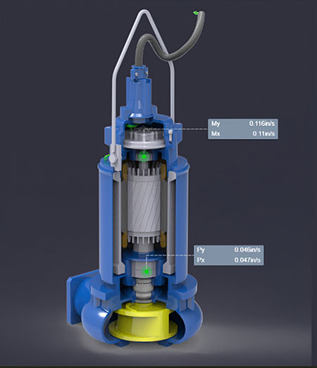
With these challenges in mind, a solution was developed that uses wired accelerometers connected to an aboveground wireless transmitter. These submersible accelerometers and wireless communication devices were provided to the steel mill to better monitor mechanical performance in the submerged condition. Real-time vibration levels on the pump and motor were continuously collected using this system. The data collected was wirelessly transmitted to the cloud for remote access, storage and analysis on an automated basis, with measurements being taken at high-frequency intervals.
The monitoring provided went beyond hardware and software to take advantage of the human experience of the aftermarket service company’s engineering team. These engineers and the end user worked together to trend mechanical vibration levels, correlate the data with the submergence level and other hydraulic parameters and detect early signs of degradation in bearings and other components.
Cost-Savings Theory Turned Into Practice
The goal of the submersible monitoring project was simple: detect issues before they become catastrophic failures and save money (and headaches) for the end user. The remote monitoring proved its value when the condition monitoring team predicted an imminent bearing failure, and the site was able to mobilize before catastrophic damage to the pump occurred.
A bearing defect was captured by the sensors and transmitted to the user through the analytical software. Bearing failures are usually observed in four discrete stages. Stage one is typically quite subtle and caused by surface-level defects that are part of the manufacturing process; there may be high-frequency waves present between 5 and 40 kilohertz (kHz).
Stage two begins to correlate to damage conditions that can be directly observed; acceleration in the 1 to 5 kHz range may present as a raised noise floor with discrete frequency excitation at run speed harmonics and/or bearing fault frequencies. Notably, impacting may be observed in stage two.
Stage three shows more overt signs of degradation, now in the velocity spectrum, as bearing fault frequency excitation becomes more severe. Sidebands can be present in the spectrum around the bearing fault frequencies, and impacting in the waveform is more severe. This is a typical point to schedule maintenance to remedy the condition/issue.
The final stage, stage four, shows vibration levels at running speed (1X) and possibly harmonics of run speed. At this stage, the damage can be so extensive that the vibration signature experiences high levels of noise and inconsistent phase angles that resemble looseness. Failure is imminent and may result in cascading component damage or worse.
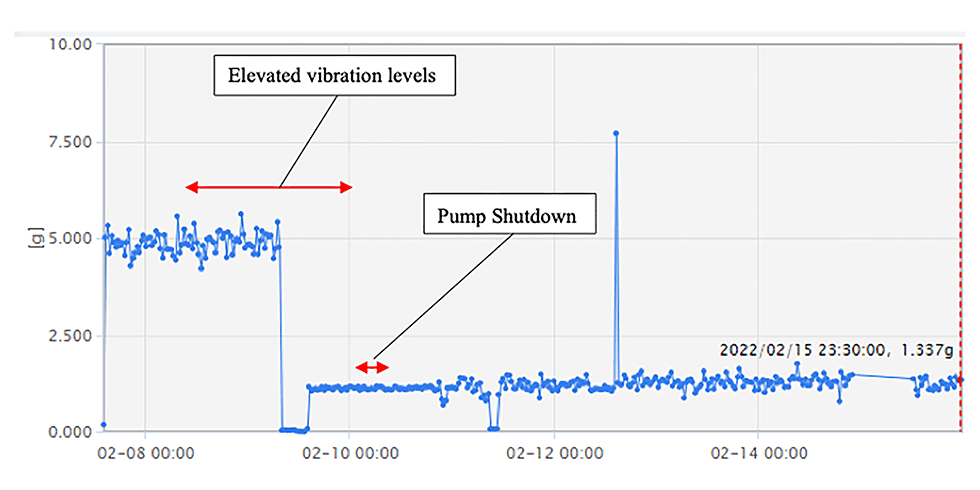
Shortly after commissioning the condition monitoring system, one of the four pumps experienced dynamic vibration amplitude levels that surpassed several alarm thresholds. The alarm thresholds are programmed into the software to allow immediate response to changing and adverse conditions. When any alarm threshold is breached, an automated alarm notice is sent out by the software to the end user and monitoring team. In this case, condition monitoring engineers analyzed the alarm condition and recommended immediate action to the end user.
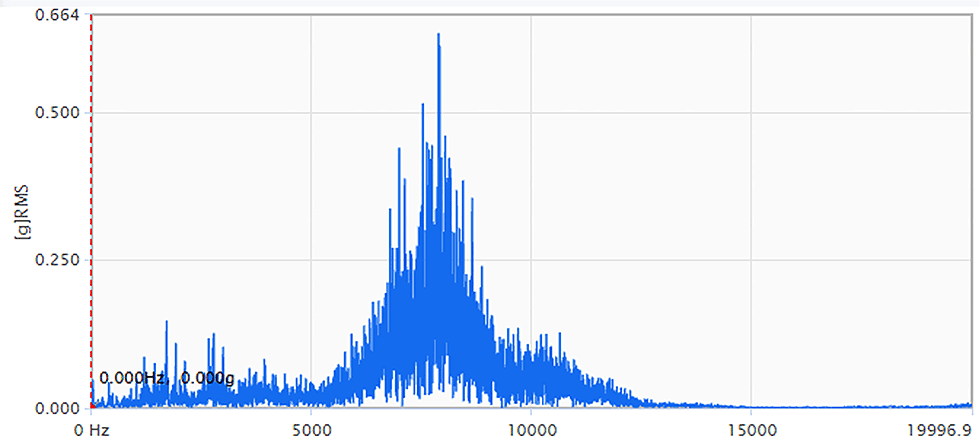
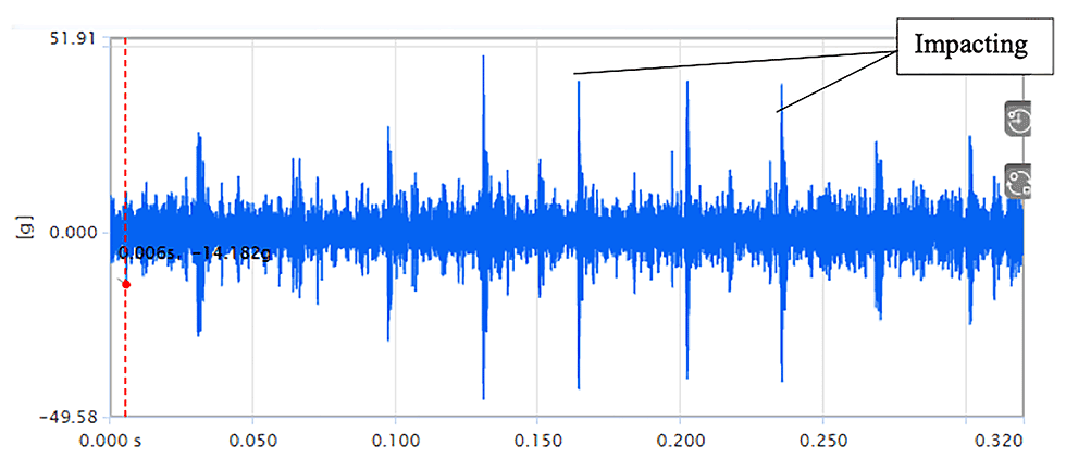
As displayed in the spectrum in Image 5, high energy vibration levels with an elevated noise floor were detected, indicative of a bearing failure. The spectrum plot is accompanied by the time waveform (waveform) plot in Image 6, which shows the occurrence of vibration energy once per revolution. The energy excitation is a result of impacting occurring in the rolling element bearing.
The condition monitoring team notified the user of the emerging issue and recommended that the pump be shut down for further inspection. The pump was shut down the day after the initial alarm was triggered and was subsequently sent to an aftermarket service center.
The recommendation proved to be accurate. Inspection revealed that there was minor seal leakage and contamination found in the bearing. The debris had caused rubbing and a gall in the bearing. Because the condition of the pump and motor showed relatively minor damage, it allowed for a straightforward pump repair, avoiding the cost and lead time of a new pump and motor from the manufacturer.
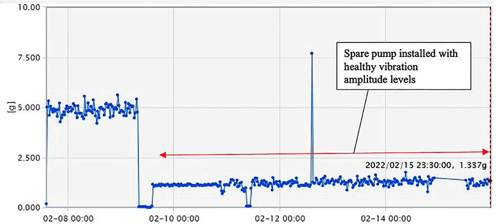
While the damaged unit was repaired, a spare was installed to replace the problem pump. Without an available spare, it was now essential that all other pumps performed well. Condition monitoring allowed the end user to continue monitoring the system 24/7. Image 7 shows that the overall vibration amplitude levels of the spare unit were acceptable.
Because they were able to predict impending failure and remove the pump for refurbishment before significant damage occurred, the end user received a repaired machine for a fraction of the cost of a new one and on a more expedient and responsive timeline. In addition, the fast turnaround time on the repair allowed the end user to have an available spare ready on-hand, should there be another pump failure.
The forward-thinking implementation of condition monitoring technology for these submersible pumps helped the end user maintain process uptime, improve equipment reliability and reduce the overall cost of maintaining this critical system.
