How one utility balanced diverting water and protecting wildlife.
Tsurumi Pumps

Upgrading a system at a dam while also protecting the fish and wildlife in an area can be a challenge.

The San Francisco Public Utilities Commission (PUC) recently faced this dilemma at Cherry Dam, which is part of the Hetch Hetchy Regional Water System, located three and a half hours east of San Francisco on the border of Yosemite Valley, California. Cherry Lake provides drinking water for the greater San Francisco Bay Area.

The outlet facilities at Cherry Dam, which were built in 1956, reached the end of their service life and, to satisfy stream-release requirements established by the U.S. Department of Interior, the 66-inch hollow-jet valves had to be removed and replaced.

PUC contracted Anvil Builders, a San Francisco-based general contractor, to coordinate the Cherry Dam Project. According to Anvil, the initial project involved removing and replacing two large 66,000-pound valves and also the replacement of various ancillary components. This included the installation of reinforced-concrete deck gussets and overhead pipe supports in the valve-house; demolition of the existing instream flow-release system; installation of the new downstream flow-release system, including piping, valves and fittings; and the removal and replacement of the alternating current (AC) distribution panel and lighting systems.

But as Anvil’s team prepared to work on the replacement of the two hollow-jet valves, they discovered a problem.

“In order to replace the hollow-jet outlet valves, we needed to close two other butterfly valves that were holding the reservoir water back,” said Caleb McWaters, Anvil project manager for the Cherry Dam Project. “In the beginning of the project, we discovered that the butterfly valves were not working, so we had to get in to fix them as well.”

For safety, the reservoir had to be drained below the intake tower, allowing dry access to the butterfly valves. However, with the water level lowered below the intake tower, no water was flowing over the dam. The challenge was to keep water flowing into the stream below the dam to support the downstream fish and wildlife while diverting water away from the repair work being performed on the valve system.

electric submersible pumps
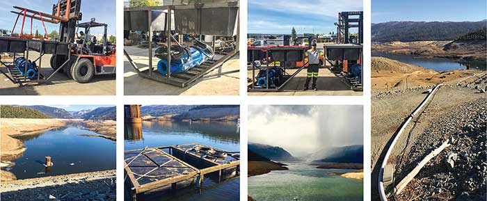
Electric submersible pumps upgraded the system at Cherry Dam and protected fish and wildlife. (Images courtesy of Tsurumi America Inc.)

Moving the water over the dam with a temporary pump bypass of the intake tower was essential, but would not be simple. The pumps needed the ability to push water up to 300 feet vertically­—276 feet plus friction losses—to get from the surface of the water from the low lake level to the top of the dam. There was not an immediate solution for how to pump the water up and over the dam. Several companies told the project team that diesel engine driven centrifugal pumps were the typical solution for this kind of job.

This was not a good solution because of the environmental impact of running diesel engines near a drinking water source and wildlife ecosystem. Specific concerns were potential diesel fuel spills, exhaust emissions, oil leakage and noise. So Anvil looked for an alternative.

The team reached out to Patrick LaZansky of Herc Rentals Inc. in Roseville, California. The company specializes in submersible pump applications when environmental factors play an important role in the job.

“The main challenge was to provide a pumping system capable of maintaining 5 cubic feet per second of water up and over the dam in order to keep water running for fish and wildlife,” LaZansky said. “It is a big deal in California to keep fish water flowing so the system could not fail. The right way to do this job was with electrical submersible pumps because they are more efficient for this application. The pumps could run on overhead line power, so a primary diesel generator wouldn’t be necessary. Once Anvil saw that I was confident and could provide an alternate solution [to diesel pumps], they were relieved that this was an option.”

An electric submersible pump would help solve the environmental issues, but also offered other advantages. There was no need to prime the pump once it was in the water, which made it more reliable.

The pump needed to push the water straight up 300 feet and work continuously throughout the duration of the project, which could be months. “This was such a risky job with all the environmental concerns and high pressures. I needed to ensure that I had specified the right pump,” he said.

The submersible pumps handle medium to high flows at higher heads, but the flow-through design allows low water level operation for extended periods. Two 150-horsepower (hp) submersibles with a discharge bore size of 8 inches were recommended. A third pump would be on standby, in case either of the others encountered a problem.

While this is not an unusual application for this submersible pump, it was unusual for a rental fleet to have this pump model available. Each pump measured 2 feet in diameter, 6 feet tall and weighed 2,750 pounds. LaZansky needed to figure out how to get these large pumps in place.

“We manifolded the pumps onshore and ran 3,500 linear feet of 12-inch high-density polyethylene (HDPE) pipe up and over the dam, with a discharge point lower than the level of the pumps,” LaZansky said. “This meant that once the pumps were running, there wasn’t nearly as much head.”

Then, custom-fabricated rafts floated the pumps on the reservoir. The rafts were also fitted with protective “fish screens” to keep fish from being pulled into or damaged by the pump intakes during operation.

The power source was a 20-kilovolt (kV) high line that provided a temporary stepdown transformer to 480 volts. The dedicated power line eliminated the need for generators, which kept costs down over the use of a diesel pump that would require frequent refueling and maintenance.

All three pumps ran on variable frequency drives (VFDs) so the pumps could be sped up or slowed down as needed. An 800-amp transfer switch was used and a standby 400 kilovolts amperes (kVA) generator was on hand for backup power. The automatic transfer switch would transfer to generator power in the event of a power line failure. The distance from the automatic transfer switch to the VFD panels was approximately 2,000 linear feet.

Pipes, manifolds, control panels and the automatic transfer switch were checked daily to ensure proper operation. No other maintenance was necessary.

The project started Sept. 1, 2017 and was expected to take three months. The project went on longer, and the pumps ran through the fall and winter in the mountains, amid heavy snow and ice, for nearly five months during the project.

“The project could not have gone better,” LaZansky said. “Worries were put to rest as soon as we turned on the pumps, and they worked flawlessly.”