

Dual pressurized pump gas seals that use technology adapted from compressor gas seals are more common in the shaft sealing industry. These seals can provide zero emissions of the pumped fluid to atmosphere, offer lower frictional drag on the pump shaft and operate with a simpler support system. These advantages deliver a solution with an overall lower life cycle cost.
These seals work by introducing an external source of pressurized gas between the inboard and outboard seal face pairs. Special surface topography features on the seal faces further pressurize the barrier gas causing the seal interface to separate, resulting in the seal faces floating on a film of gas. Since the seal faces are no longer in contact, frictional losses are low. Barrier gas flows across this film at a low flow rate, consuming the barrier gas that appears in the form of leakage—the majority of which is leakage across the outboard seal faces to atmosphere. The balance leaks into the seal chamber and is eventually carried away in the process stream.
Advantages of Pump Gas Seals
All dual pressurized seals need a pressurized fluid (liquid or gas) introduced between the inboard and outboard face pairs within a mechanical seal assembly. To deliver this fluid to the seal, a support system is needed. In contrast, liquid-lubricated dual pressurized seals circulate the barrier liquid from a reservoir through the mechanical seal, where it lubricates the seal faces, absorbs heat, and then returns to the reservoir where the absorbed heat needs to be dissipated. These support systems for liquid pressurized duals seals are complex. The heat loads increase as pressure and process temperatures increase, which can lead to reliability issues if incorrectly sized and installed.
The support system for dual pressurized gas seals has a small footprint, requires no cooling water, and has almost no maintenance requirements. Also, its reliability is independent of process pressure and temperature when supplied with a reliable barrier gas source.
Dual Gas Seal Support System
With the increased adoption of dual pressurized pump gas seals in the market, the American Petroleum Institute (API) added Plan 74 as part of the release of the second edition of the standard API 682.
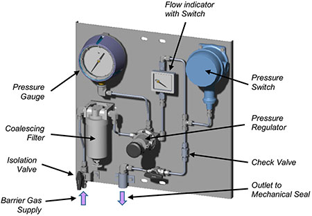
A Plan 74 support system is typically a panel-mounted group of instruments and valves that clean the barrier gas, regulate the outlet pressure and measure the pressure and gas flow delivered to the mechanical seal. Following the path of the barrier gas through the Plan 74 panel, the first item is an isolation valve. This allows the supply of barrier gas to be isolated from the seal for replacement of the filter element or maintenance of the pump. The barrier gas then flows through a 2 to 3 micrometer (µm) coalescing filter to trap liquids and particles that can damage the seal face topography features that create the gas film at the seal face interface. Next is a pressure regulator and pressure gauge that sets the delivery pressure of the barrier gas to the mechanical seal.
Dual pressurized pump gas seals require a barrier gas supply pressure that meets or exceeds the minimum pressure differential above the maximum seal chamber pressure. This minimum pressure differential varies with seal manufacturer and seal type but is typically around 30 pounds per square inch (psi). A pressure switch is used to detect any problems with the supply barrier gas pressure and alarm if the pressure drops below the minimum pressure.
The performance of the seal is monitored by barrier gas consumption rate using a flow meter. Deviations away from the normal barrier gas consumption rate provided by the mechanical seal manufacturer indicate degrading seal performance. A decrease in barrier gas consumption can be the result of the pump spinning backward or liquid migrating to the seal interface (either from contaminated barrier gas or the process fluid).
Typically, after these types of events, damage occurs to the seal face and barrier gas consumption then increases. Damage to the seal faces can also occur as a result of pressure spikes in the pump or partial loss of barrier gas pressure. A high flow alarm can be used to determine at what point intervention is needed to rectify the high gas consumption. The set point for the high flow rate alarm is typically in the range of 10 to 100 times the normal barrier gas consumption rate, and it generally is not determined by the mechanical seal manufacturer but rather how much gas leakage into the pump can be tolerated.
Traditionally, variable area flow meters are used, and it is not uncommon to see a low-range and a high-range flow meter connected in series. A high-flow switch can then be fitted to the high-range flow meter to signal a high-flow alarm. Variable area flow meters can only be calibrated for a specific gas at a specific temperature and pressure. When operated at other conditions, such as temperature variations between summer and winter, the displayed flow value cannot be considered a precise value but rather something near the actual value.
With the release of API 682 4th edition, both flow and pressure measurement have changed from analog to digital with a local readout. Digital flow transmitters are available as either a variable area flow meter that has the float position converted to a digital signal or a mass flow meter where the mass flow is automatically converted to a volumetric flow. A nice feature of mass flow transmitters is that the output provided can compensate for pressure and temperature giving a true flow rate at standard atmospheric conditions. The drawback is that these devices are more expensive than variable area flow transmitters.
The challenge of using flow transmitters is finding one that can measure the barrier gas consumption rate during normal operation and at the high-flow alarm point. Flow transmitters have maximum and minimum values that they can accurately read. Between zero flow and the minimum, the output flow value may not be accurate. The catch is that when the maximum flow value increases for a particular flow transmitter model, so does the minimum flow value.
One solution is to use two transmitters (a low range and high range), but this is an expensive option. A second method is to use a flow transmitter for the normal operating flow range and a high-flow switch with an analog high-range flow meter. The last component the barrier gas flows through is a check valve before the barrier gas exits the panel and connects to the mechanical seal. This is to prevent reversing flow of the pumped fluid into the panel and damaging the instruments if an abnormal process upset were to occur.
The check valve needs to have a low cracking pressure. If incorrectly selected, or if the dual-pressurized pump gas seal has a low barrier gas consumption rate, pulsations in the barrier gas flow rate can be seen as a result of the check valve cracking open and reseating.
Barrier Gas
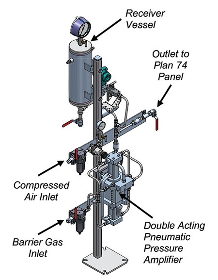
Typically, plant nitrogen is used as the barrier gas since it is readily available, is inert and does not create any adverse chemical reactions in the pumped fluid. Less readily available inert gases, such as argon, can also be used. In cases where the required barrier gas pressure is greater than the plant nitrogen pressure, a pressure amplifier can boost the pressure and store high-pressure gas in a receiver that is connected to the Plan 74 panel inlet. Banks of bottled nitrogen are not generally recommended, as they require the constant changing out of empty bottles with full ones. If the seal experiences any degradation in performance, the bottles can be emptied quickly, forcing the pump to be stopped to prevent further damage and failure of the mechanical seal.
Installation & Commissioning
Unlike liquid barrier systems, a Plan 74 support system does not need to be immediately adjacent to the mechanical seal. The only note of caution here is with extended runs of small-bore tubing. A pressure drop between the Plan 74 panel and seal can occur in the tubing during high flow (deteriorating seal performance) that can reduce the barrier pressure margin being delivered to the seal. Increasing the tube size can eliminate this concern. Typically, the Plan 74 panel is mounted on a stand at a comfortable height to operate the valves and read the instruments. The stand can be mounted on the pump baseplate or adjacent to the pump in a location that does not affect inspection and maintenance activities for the pump. Avoid creating trip hazards with the pipe/tube that connects the Plan 74 panel to the mechanical seal.
For between-bearing pumps that have two mechanical seals, one at each end of the pump, it is not recommended to use a single panel and split the barrier gas outlet to each mechanical seal. The recommended solution is to use either a dedicated Plan 74 panel for each seal or use a Plan 74 panel that has two outlets, with each outlet having its own set of flow meters and flow switches. Winterizing the Plan 74 panel may be required for sites subject to cold winters. This is primarily to protect the panel’s electrical devices and typically takes the form of encasing the panel in an instrument box and adding heating elements.
One interesting phenomenon is that barrier gas consumption rate increases with decreasing barrier gas supply temperature. This generally is unnoticed but may become apparent at sites with cold winters or large differences in temperatures between summer and winter. In some situations, this may require adjustments of the high-flow alarm set points to prevent nuisance alarms. Before commissioning the Plan 74 panel, the panel piping and interconnecting pipe/tube need to be purged of air. This is most easily accomplished by adding a vent valve at or near the connection to the mechanical seal. If a vent valve is unavailable, the system can be purged by disconnecting the pipe/tube from the mechanical seal and then reconnecting after purging.
With the Plan 74 panel connected to the seal and all fittings leak checked, the pressure regulator can now be adjusted to the set pressure for the application. The panel must deliver pressurized barrier gas to the mechanical seal prior to flooding the pump with process fluid. Once the pump commissioning and venting procedures have been completed, the seal and Plan 74 panel are ready for startup.
Operation
After one month of operation, the filter element should be inspected, and if no contamination is detected, inspection should occur every six months. The filter element replacement interval will be dictated by the cleanliness of the supply gas but should be no more than three years.
The barrier gas consumption rate should be checked and recorded during routine inspections. If the pulsations in barrier gas flow caused by the check valve opening and closing are large enough to trigger high-flow alarms, these alarm values may need to be raised to avoid nuisance alarms.
Decommissioning for Maintenance
The key step for decommissioning is that isolation and removal of the barrier gas pressure should be the last step. First, isolate and depressurize the pump casing. Once the pump is safe, the barrier gas supply pressure can be isolated and gas pressure vented from the piping connecting the Plan 74 panel to the mechanical seal. Drain any liquids from the system before commencing any maintenance activities.
The combination of dual-pressurized pump gas seals together with the Plan 74 support system offers operators a shaft sealing solution that provides zero emissions to atmosphere; lower capital investment (compared to seals with a liquid barrier system); lower life cycle cost; a small footprint for the support system; and little maintenance requirements.
When installed and operated with best practices, this sealing solution can deliver long-term reliability and improved rotating machinery availability.
We invite your suggestions for article topics as well as questions on sealing issues so we can better respond to the needs of the industry. Please direct your suggestions and questions to sealingsensequestions@fluidsealing.com.'
