

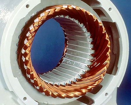
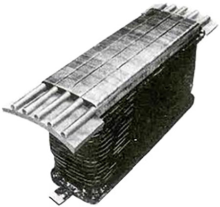
IMAGE 1 (top left) : Permanent magnet synchronous motor (Images courtesy of All-Test Pro). IMAGE 2 (top right): Separately excited synchronous motor
The June 2022 issue of Pumps & Systems published an article discussing the expected growth in the use of synchronous motors in the pumping marketplace called “The Advantages of Synchronous Motors.” This article is the first of a two-part series and provides a brief overview of the construction and operation of synchronous motors, common faults and how synchronous motors can be used to adjust the plants electrical systems power factor.
The second part will discuss how motor circuit analysis can be used to assess the current condition of these motors as well identify any developing issues easily and quickly before they become problematic.
Advantages of Synchronous Motors in Pumping Applications
Synchronous motors are normally used when constant speed operation is required; however, for pumping applications, they are primarily being used for financial considerations, such as:
1 - Higher efficiency operations than are typically performed by induction motors, which results in lower energy costs.
2 - Ability to improve system power factors to help mitigate any power factor (PF) surcharges imposed by the energy supplier. This allows a single motor to supply the required flow from the pump as well as improve the plants power factor.
Power Factor Correction
Power factor is defined as the ratio of true power (watts) divided by apparent power (volt amps). The main issues are that plants that normally pay for true power use kilo watt hours (KWH). The difference between real power and apparent power is reactive power. To quickly review:
True power (Watts) is the power producing useful work, transferred to the load, and is measured in watts.
Reactive power (VARs) is the power required to create the magnetic fields in motors, transformers or any coil in the electrical system. This power is stored power as a magnetic field and causes the current to lag the voltage. Any capacitance in the circuit will also store power and cause the voltage to lag the current. If there is more inductive load in the system, the PF is lagging. If there is more capacitive load in the system, the PF will be leading. The units for reactive load are volt-amps reactive.
Apparent power (VAs) is the total power supplied to the system from the source. This is supplied voltage multiplied by all of the current in the system.
Power factor (PF) is the ratio of the true power used in the system to the apparent power supplied by the source and is measured in percent. PF = (true power/apparent power) 100
The utility needs to supply the plant with apparent power but only charge for true power used. Ideally, the utility would like to charge the user with all the power supplied, but plants with low factors require the supplier to maintain sufficient capacity to provide the required apparent power but can only charge for the true power. So, when a plant operates near a unity power factor (true power = apparent power), the supplier is charging for the total capacity supplied. In plants that operate with low power factors, the supplier is not charging for the additional capacity required, so they add a power factor surcharge.
Most industrial operating plants have a large population of inductive loads, meaning they will have a lagging power factor. Synchronous motors can be used to move the PF from a lagging PF by over-exciting the rotor field coils.
Basic Types & Construction of Synchronous Motors
Since synchronous motors rotate at the same speed as the rotating magnetic field, it is necessary to have a magnetic field on the rotor. Synchronous motor types are:
1 - Nonexcited synchronous motor: The most common of these are permanent magnetic synchronous motors, which have permanent magnets mounted on the rotor to create the rotating magnetic field.
2 - Separately excited synchronous motor: These have a series of field coils wrapped around the rotor field poles and require a direct current (DC) voltage to create the magnetic field on the rotor. These motors can further be subdivided as brush-type or brushless exciters.
Basic Construction of Synchronous Motors
The basic construction of the stator is the same as any three-phase alternating current (AC) motor. There are three sets of phase windings like a standard three-phase induction motor. These coils are precisely placed in the stator slots to create three-phase windings, each phase having an even number of poles (P).
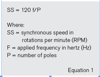
Applying three-phase AC power directly to the phase windings creates a magnetic field that rotates at a constant speed around the stator core. This is referred to as synchronous speed (SS). The SS is dependent on the number of poles and the applied frequency.
The main difference between an induction motor and a synchronous motor is the rotor. The rotor is placed inside the stator core and mounted on bearings to position the rotor in the geometric center of the stator core, which allows the rotor to rotate freely.
Permanent magnets or field poles create a rotating magnetic field, which interacts with the magnetic field rotating around the stator. The interaction between the two magnetic fields converts electrical energy into mechanical torque.
Separately excited rotors can be subdivided into brushless or brush-type synchronous motors. The brushless types normally have a rotating AC alternator mounted on the motor shaft. These alternators have armature coils mounted of the shaft with its field supplied from coils on the stator. The AC output generated power is then rectified to supply the required direct current (DC) field excitation to the motors field coils.
The brush type synchronous motor applies a DC voltage through brushes riding on slip rings to the field coils mounted on the field poles to create the rotor magnetic fields. The field coils, which create magnetic fields on the rotor poles, are connected in series with adjacent poles being the opposite polarity, as shown in Image 2.
A disadvantage of synchronous motors is insufficient torque available during start up to turn the rotor with a load applied. During startup AC, the synchronous motor reacts the same as an AC induction motor. It relies on a specialized circuit created by the amortisseur windings to build a magnetic field on the rotor.
The amortisseur windings are conductors imbedded in the face of the field poles that act as conductors during the startup cycle. The amortisseur windings are connected on each end to create an electrical circuit like those used in squirrel cage induction motors.
The starting current relies on Faraday’s law of mutual inductance to create the same high starting current created in induction motors. This allows the shaft’s rotational speed to catch up to the rotating magnetic field. When the rotor approaches synchronous speed, the DC field is applied to the rotor field coils, allowing the rotor to field poles to lock on to the rotating magnetic field.
Synchronous Motors Faults
As with most motors, the bearings are generally the major cause of synchronous motor failure, followed by rotor and stator coil winding shorts. Additionally, the amortisseur windings can crack just as when rotor bars fail in induction motors.
Identifying these faults with the traditional electrical testing devices and instruments commonly used throughout the industry have the limitations and drawbacks encountered on squirrel cage induction motors. However, due to their construction and operation, additional testing techniques and methods are required.
Machinery vibration analysis techniques have advanced the detection of identifying rolling element bearing faults, and the same motor circuit analysis (MCA) that has similarly advanced the detection and analysis of induction motors can be applied to synchronous motors
MCA is effective in locating and identifying motor faults in induction motors. This same technology can be applied to the expanding population of separately excited synchronous motors. Specialized MCA tools have been developed to evaluate and troubleshoot the smaller permanent magnet synchronous motors used in electric vehicles and many other plant applications.
MCA uses a series of low voltage AC and DC voltages to exercise the insulation surrounding the conductors in the stator and the rotor field coils. MCA identifies the small changes that occur in the chemical makeup of the winding insulating material as the insulation between the conductors degrades. MCA measurements and tests identify:
- developing rotor and stator winding shorts
- broken/cracked amortisseur windings
- air gap dynamic/static eccentricity
- condition of the groundwall insulation
Part 2 of this series will provide how MCA can be used to identify and evaluate the above faults.
