

The piping system tells the pump where to operate on its performance curve. The physical system can be represented geographically by a parabolic curve and is referred to as the system friction curve or, more commonly, the system resistance curve (SRC).
I start my pump training courses with the statement that pumps are dumb. It is the system, not the pump, that dictates where the pump will operate on its performance curve—if the pump is even capable of operating at that point.
The pump will operate where its performance curve intersects the system curve. We don’t always know where the point of intersection is—and just to complicate matters, it can quickly change due to a plethora of variables. For more information, see my August 2019 column, “Why Is Your Pump Operating Off the Curve?”
Knowledge of the system curve shape and position is crucial to solving numerous field problems. If you are responsible for pump reliability and have never tried to calculate the system curve for one of your processes, then this column can serve as the impetus to prime your educational journey.
Determining the actual pump operating point (head and flow) is a critical step in problem solving. If the pump is not worn out and the system was properly designed and operated in the first place, then simply measuring the differential pressure (head) across the pump (discharge head minus suction head = total head) will get you close on the pump curve, but that information only yields one point on the system curve.
For this two-part column, we will examine the three main factors that make up a system curve for a single centrifugal pump in an open system with a flooded suction. I will cover the first two factors (the easy ones) this month and friction (the difficult one) next month.
General System
In the field, I often encounter systems that were designed correctly, but over time, revisions were made to the initial design without consideration for reliability or long-term operating/maintenance costs. Unfortunately, I have also experienced system designs that were doomed to fail from the start. When solving a pump system issue, I will often request a copy of the system curve from the owner. However, it is a rare occurrence when the system operator knows what the system curve is and/or where it is. Consequently, we spend the next few hours “walking the system” and developing the system curve. More discussion on “walking the system” next month.
Some designers will design the piping system first and then pick the pump, while others will do the opposite. A smart choice would be to do both at the same time. The project design process will dictate the basic system parameters and economics (think optimum pipe size). Decisions regarding the system lifespan should be guided by the required/desired level of reliability balanced with the estimated total cost of ownership.
System Curve
The system curve is composed of three basic factors: the static head (elevation head), the pressure head and the friction head (pressure drop).
Simply stated, a system curve defines the relationship between total head loss and flow rate.
A system head curve is a cartesian (graphical quadrant 1) representation of the head required by the system over the full range of design flow rates.
The system curve displayed as a graph portrays the functional relationship between the flow rate and the aggregate combination of heads from static, pressure and friction.
In conventional practice, the flow rate (Q) is assigned to the horizontal X-axis and the head (H) is on the vertical Y-axis. For non-return open systems with a flooded suction, the total pump head is the sum total of all friction losses plus the static head and the pressure head, but for a closed loop system, it is simply the
friction losses.
Technically, there is a fourth system curve component of velocity head which can be ignored for this “101” version of system curve calculation because in a properly designed system, it is normally a negligible factor.
Draw the System Curve
You can create the system curve on a sheet of graph paper and then add the pump curve. Alternatively, I like to just draw the system curve (superimpose) on a printed copy of the pump curve. The latter
method can be a little messy, but the head and flow axes with assigned values are already established.
Reflection: Many of you may question my old school choice of graph paper, and I will acquiesce that you may wish to simply do the work in Excel (or the worksheet of your choice). I still have pads of engineering graph paper left over from my college days (circa 1969) in addition to a box of IBM key punch compiler cards for my Fortran projects. I am trying to consume these items before I completely retire.
Static Head
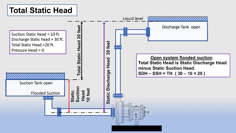
Static head is sometimes referred to as elevation head and is independent of the flow rate. This first factor in the system curve calculation is relatively easy to cipher and requires only a physical measurement. Briefly described, static head is the difference in the vertical height (change of elevation) from the liquid surface level of the suction source to the liquid surface level of the discharge point.
Another perspective is that the total static head is the difference between the static suction head and the static
discharge head on a flooded system. See Image 1 and the comments and caution notes below for more information.
Static head is the net change in height that the pump must overcome. In the United States Customary Units (USCU) system, the units are feet, and in the International System of Units (SI), it is expressed in meters.
Static head is only applicable for open systems and variances thereof. Note that in a closed loop system like a hydronics system, the static head is zero because the pump does not need to overcome any elevation when viewed as a total system. One part of the system pushes the fluid up, and on the other side of the system, gravity pulls it down for a net zero sum.
Comments & Caution Notes
By definition, a “flooded suction” simply means that the liquid level on the suction side is above the pump impeller centerline. It does not imply there is adequate net positive suction head available (NPSHa) and/or submergence as many people believe.
Note: On the suction side of the pump, the amount of vertical distance (height) of the liquid above the pump centerline can be subtracted from the vertical distance the pump must move the liquid on the discharge side.
If the suction side liquid level was below the pump centerline (deemed a suction lift), then the vertical distance would need to be added because that is work that the pump must perform.
When determining static head, we don’t care what shape the pipe or vessel is or if there is significant horizontal distance. This simple factor is solely the difference in elevation.
Static head (total, suction or discharge) is measured in the absence of flow, that is, under static conditions with the
pump off.
The distance component (X-axis) length of horizontal pipe will get captured later in the friction factor. For now, we are simply concerned with the gravitational effect on the liquid.
On the discharge side of the pump, you need to consider the height from the centerline of the pump to the highest point in the system. If you are pumping into a tank/vessel (like in the illustration), the highest elevation would typically be the liquid level in the tank. However, in many processes, the pump discharge is open above the tank, so the pipe discharge level is the high point.
Caution with minimum and maximum levels: when you take the measurements, you are capturing a static moment in a dynamic system. Always consider the worst case, that is, “is the suction tank at its lowest or highest point?” Then, ask again for the discharge tank level or point. Yes, you could have multiple system curves, due to differences in static head, depending on the system dynamics, and therein lies one of the issues to be discerned. Most systems are not completely defined by a single line system head curve (particularly applicable when considering the friction head).
Technically, we need to measure from the centerline of the impeller as our datum point, and in many cases, that is also the centerline of the pump. However, this is not always the case. For example, a vertical pump, some self-primers and/or a horizontal split case pump.
Sometimes, and for valid reasons, pumps are used to pump liquid downhill. In that case, the static head will actually be a negative value (Cartesian quadrant 4).
Drawing the Line for Static Head
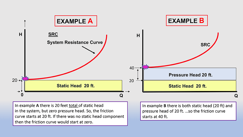
Assume for our example that the total static head is 20 feet; you would then draw a horizontal line with starting point on the vertical Y-axis at value 20 feet across the full graph. This line is not the system curve per se; it is simply a reference point.
Pressure Head
The second factor in the system curve calculation is the pressure head. For a true open system (free and unrestricted discharge), there is no pressure head, so we can ignore the factor and no action is required. However, in a hybrid open system, if there is pressure head, then the pressure would be converted to head and added to the static head. To accomplish this task, simply multiply the pressure by 2.31 and divide by the specific gravity to arrive at the number. My personal and conservative practice is to add a small additional amount of head to the number because the pump has to actually overcome the pressure head, not just meet it.
Similar to static head, it is assumed that the pressure head does not change with the pump flow rate; therefore, it is a straight-line function. Further, it is not the system curve but a reference point for the initiation point of the friction curve (Image 2).
Common examples of pressure head would be a boiler feed system where the boiler has internal steam pressure that must be overcome by the pump or a condensate pump overcoming the pressure of a deaerator.
The last and key component for the combined SRC is the friction curve.
Next month, I will explain “walking the system” and also how to calculate the friction portion to complete the full system curve.
Side note:
In simple terms, velocity head is the energy required to accelerate the fluid from zero or low velocity (at the pump suction) to a higher velocity downstream in the system. Velocity head is the kinetic factor in Bernoulli’s equation (conservation of energy principle appropriate for flowing fluids) that is one factor of three in the total head. Velocity head is typically calculated because it cannot be measured by a standard pressure gauge configuration. Note that velocity head is zero in closed loop systems. Should you wish to learn more, please read my column from April 2020 “The Three Musketeers.”
References
Cranes Technical Publication 410
Cameron Hydraulic Data Book
Hydraulic Institute Engineering Data Book
Pumping Station Design 3rd edition, Garr M. Jones et al
