
The changing landscape of hydraulic drives is leading many fluid power specialists to quickly adapt to VSDs.
11/16/2015
Despite ominous predictions in the 1980s and '90s, the complete replacement of hydraulics with electrical drives did not occur, and fluid power still plays an important role in modern drive technology. When large forces and high torques are required, hydraulic drives are irreplaceable because of their enormous power density. During the last 30 years, the field of traditional hydraulics has evolved into electro-hydraulics, the integration of electronics and closed-loop controls. This integration has become an industrial standard. Combining strength and intelligence, modern fluid power drives are perfect examples of highly integrated mechatronic devices.
Advanced Solutions
Ongoing competition with electrical drives and ever-increasing performance and energy efficiency requirements have led the hydraulic drive industry to more advanced system solutions. Electrohydraulic drives typically use resistive or volumetric power control. In resistive control, a valve—usually a proportional device—controls the system by throttling oil flow delivered from a power supply source. In volumetric control, flow is controlled by adjusting the displacement of a pump or by directly changing the drive speed of a fixed or variable displacement pump. Resistive control has excellent dynamic characteristics but poor energy efficiency. Heat dissipation from throttling the hydraulic fluid in the control valve can cause significant energy costs associated with cooling the hydraulic equipment, fluid reservoir and equipment spaces. A number of broad manufacturing trends are influencing the increased interest in and potential value of pump variable speed drives (VSDs). Rising costs of energy and increased awareness of environment issues has resulted in new trends in drive systems. During the last two decades, improvements in electrohydraulic efficiency were a main goal of many companies and research institutes. Given advances in drive technology and closed-loop control, efficient volumetric control using speed variable pump systems is replacing the resistive throttling method. Reducing throttling losses lowers the amount of heat transferred to the oil and oil reservoir. Lower heat generation allows for a smaller capacity cooling system and lower parasitic power needed to maintain optimum oil temperature. Using variable frequency drives (VFDs) with hydraulic power units can also lower average noise emissions, as the pump speed is reduced during partial load operations, such as pressure holding or idling. The average sound level can be lowered by as much as 10-20 dB(A), improving environmental working conditions.Growth of VSDs
The combination of advanced electric drive technology and hydraulics opens a new chapter in electrohydraulic drive systems. Machine builders can benefit from both the traditional hydraulic characteristics of robustness and power density and the advantages of electric drives: inherent drive intelligence and ease of integration with factory automation systems..jpg) Image 1. A refit and customized hydraulic system (Images courtesy of Bosch Rexroth Corporation)
Image 1. A refit and customized hydraulic system (Images courtesy of Bosch Rexroth Corporation)
System Design Options
Systems using VSDs can use a number of different design solutions. The selection of the best drive and circuit design depends on a number of factors, including the type of hydraulic circuit, the required response times and accuracy and the power required. Dynamic performance and power requirements determine the choice of the motor. For applications requiring the fastest response times and highest accuracies, a PMM—used extensively in plastic injection molding machines—may be the best selection. These drive systems offer extremely high performance and have high productivity rates. Because of their high power density and low drive inertia, PMMs have the highest acceleration capabilities. These high dynamics allow complex machine control tasks, such as direct force, speed and cylinder position control, to be realized without proportional valves. The main limitation when using PMMs is maximum continuous output power, typically less than 60 kilowatts (kW). Units with output power greater than 60 kW may require multiple PMM-pump groups. Standard asynchronous induction motors driven with VFDs can be used in higher power applications, where direct control of high dynamic axes is not required. Using standard induction motors with VFDs, operating in a sensorless vector control mode (no separate motor feedback device required), results in a cost-effective system. The designer, however, should be aware of the limitations of direct control using these drives, including long system response times that result from the high inertia of the induction motor. VSDs using standard induction motors with VFDs are used in the woodworking industry, on press applications, in plastics machinery, in heavy industry applications and for machining tool applications for which the control task is typically regulating system pressure or flow.Selecting Motor Size
The motor size and drive should be selected based on the pressure-flow-time cycle (p/Q profile) for the application machine. In practice, motors on standard hydraulic power units are often sized based on corner power, which is calculated from the maximum pump pressure and flow. Duty cycle is commonly not taken into account. This results in the installation of excess motor horsepower. If partial load comprises a significant portion of the machine cycle, the excess motor power can be significant. When sizing PMMs for VSDs, users should follow methods commonly used in electromechanical actuator drives, including calculating the root mean square (RMS) value based on the load torque and average drive speed. Once a pump size is determined, the motor torque and speed are calculated from the required pump pressure and flow. The dynamic torque requirements for accelerating and decelerating the motor's rotor and pump inertia also should be added. These calculated values are used to select the proper size drive and motor. Specialized tools, which can analyze p/Q profiles and motor load factors, can be used for drive sizing and system optimization. For a more complex analysis, a numerical simulation can be used to model the system. Dynamic simulations provide more insight into system dynamics, such as pressurization, and interactions between the drive and the hydraulic system. These simulations also help with analysis of the performance of closed-loop controls. These dynamic simulations can be carried out using software that includes drive and hydraulics model libraries..jpg) Image 2. A core shooter at a foundry
Image 2. A core shooter at a foundry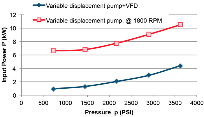 Figure 1. Using variable displacement pumps integrated with VFDs allows more efficient operation during partial load conditions, when compared with a standard variable displacement pump running at constant speed.
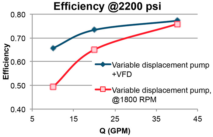 Figure 2. In recent years, the cost of using variable speed drive technology has become more economical, making it effective to combine variable speed electric drives with hydraulics.
Pump Selection Criteria
When selecting a pump for variable speed operation, several important factors must be considered:- Is the pump construction suitable for variable speed operation?
- What are the minimum and maximum allowed revolutions per minute for the pump?
- Can the pump be used bi-directionally, and, if so, are there any pressure and speed limitations?
- Is the pump suitable for start and stop operation?
- What is the maximum operating pressure allowed for the pump, and does pressure affect the maximum allowable pump speed?
- What fluid will be used in the system, and does it limit the pump's pressure and speed, based on viscosity and pump lubrication?
- What is the mechanical and volumetric efficiency of the pump at the design operating points?
- What is the pump acoustic noise level based on expected speed, pressure and displacement?
- What will the pressure and flow pulsations be over the range of operating speeds?
- Is the hydraulic circuit open or closed?
Hydraulic drive trends and considerations
Technology trends
- Intelligent electrohydraulics enables much greater control and flexibility.
- Variable speed pump drive technology provides significant energy-efficiency improvement.
- Reduction of throttling losses lowers oil reservoir cooling requirements.
- Using VFDs with hydraulic power units can lower average noise emissions by 10-20 dB(A).
Key considerations
- Dynamic performance and power requirements determine the choice of the motor.
- Select motor and drive size based on pressure-flow-time cycle (p/Q profile) for the application.
- When selecting pumps, consider suitability of pump construction for variable speed operation.
- Also consider mechanical and volumetric efficiency at the design operating points.
- Improper pump selection or operation outside allowed conditions can result in premature pump failure or suboptimal control performance.
