Pumps & Systems, February 2009
Computer simulations of pumps and compressors can now serve the same function as hardware testing. These simulations can be done in less time with less cost while providing engineering data of similar quality. Furthermore, computer modeling can be performed directly by the engineer doing the hardware design, thus providing a tight link between analysis and design optimization.
Computer Pump/Compressor Simulations
We will start by defining pump simulation. Modeling and simulation can take many forms, but in this article, pump simulation refers specifically to 3-D computational fluid dynamics (CFD), an example of which is shown in Figure 1.
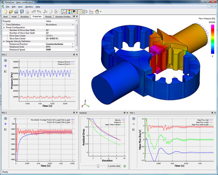 Figure 1. CFD model of an external gear oil pump (surface pressures and x-y data plots)
In this context, Computational Fluid Dynamics applies to liquid or gas, compressors or pumps, and can be used to model fluid motors and a wide range of other fluid components. Such CFD codes usually start with a CAD model of the geometry and then create a 3-D numerical mesh representing the flow path through the device. This mesh is subsequently used to model the dynamics of the flow based on fundamental laws for conservations of mass and momentum. The output of these models includes plots and three-dimensional maps of flowrates, loads, head-rise, power, pressure ripples, velocities and torques, depending on whether it is for a pump, compressor or motor.
For liquid applications, the more advanced codes include aeration and cavitation. Aeration refers to the presence of non-condensable gases, such as air; and cavitation refers to the formation of vapor from the liquid. Both can have a significant effect on pump performance and life.
If temperature influences the properties and performance, such as in compressors, the code must also solve conservation of energy equation (Figure 2).
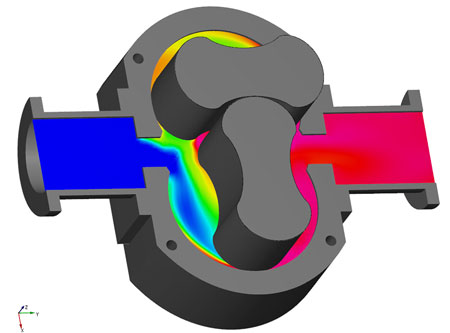 Figure 2. CFD predicted air temperature (on a cutting plane) in a lobe compressor
To be effective, CFD codes should provide the same data as a hardware test. The question is often raised, however, whether these simulation tools are sufficiently accurate, easy-to-use and fast to be used reliably as virtual hardware tests.
The Advantages of Simulation
The general advantages of computer simulations have been well established. For the majority of pump/compressor developers, computational stress simulations have been an integral part of their design process for decades. This is true for axial, centrifugal and positive displacement (PD) pumps. In contrast, the use of CFD simulation has lagged behind other computer simulation tools because of difficulty-of-use, slow turnaround time, and inaccuracies or deficiencies in the results.
Within the last few years, however, state-of-the-art pump modeling has evolved to where setting up a detailed model of even a complex pump takes less than an hour. This reduction in set-up time has been accomplished, in part, by new meshing algorithms that start with a CAD file and automatically generate the numerical grid needed for CFD. With the newer software, running a simulation on a standard desktop now takes between one hour to overnight, depending on the type of pump and the extent of the system. These statistics include both axial/centrifugal pumps and positive displacement (PD) pumps, the latter of which are more challenging to model from a numerical perspective.
Using state-of-the-art results from a good CFD code should be within 10 percent accuracy or better compared with experimental data. Accurate and quick simulation can reduce the time and cost associated with hardware testing by providing the same type of data that would be collected during testing. With simulation, it is easy to add "measurement" probes in locations that would be extremely difficult to access in a physical experiment. Perhaps most importantly, numerical simulation offers flow visualization that allows the engineer to "look" inside the pump during operation and provides invaluable insight as to how the pump operates and how it might be improved.
Validation and Application
The engineering data of interest for the modeler are the same as those of the designer and test engineer. These include flowrates, pressure ripple, efficiency, torque, power, head rise, loads, cavitation damage and cavitation onset. These same data are in turn the focus for validation of CFD tools. Figure 3 provides an example where CFD is used to predict flowrate vs. RPM in a crescent pump [1]. Comparison with experiments indicates the model accurately captures the drop in performance at higher RPMs due to the combined effect of aeration and cavitation. This type of analysis is used to improve the porting and/or system integration for a given pump design or to compare pump designs.
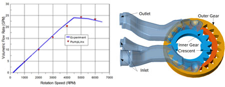 Figure 3. Flow rate predictions for a crescent pump
CFD can also predict head-rise, power and efficiencies for PD pumps and axial/centrifugal pumps as effectively as a hardware test. Figure 4, for example, compares the predicted efficiency for a centrifugal pump and shows excellent correlation with measured data [2].
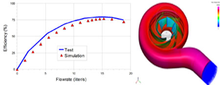 Figure 4. CFD simulation of a centrifugal pump
CFD is also used to analyze cavitation effects-perhaps even more effectively than a hardware test because CFD enables the analyst to easily visualize the cause and location of bubble formation. Cavitation can have a detrimental effect on efficiency, and it can also affect pump life through damage caused by high pressures generated as vapor pockets collapse. Cavitation has historically been a difficult problem to model, because the high density ratios between the liquid and gas can cause numerical convergence problems and accuracy issues. As a result, many codes only model up to the onset of cavitation. However, recent advances in CFD now make it possible to model robustly deep cavitation, predicting the instantaneous volume fraction of vapor and non-condensable gases (e.g. air) throughout the pump [1, 3].
Figure 5 shows a correlation between the locations of predicted cavitation (indicated by the crescent -shaped red spot inside the yellow circle) in an axial piston pump and the actual damage observed during pump testing [4]. Given the long duration it sometimes takes for cavitation damage to appear during testing or operation, numerical prediction can be a much more efficient means of assessing possible cavitation damage.
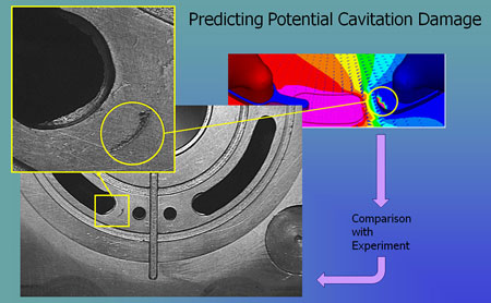 Figure 5. CFD prediction of cavitation in an axial piston pump
All the simulations in the examples above were accomplished by applying fundamental principles (conservation of mass and momentum) coupled with physical models for cavitation and/or turbulence models. These basic principles and models have been available for decades. What has changed is their implementation using more sophisticated algorithms. CFD codes for pumps and compressors have now evolved to the point where a detailed 3-D model can be run in less than a day and produce accurate engineering data that compare well with experiments over a wide range of operating conditions.
Integrated CFD for Every Designer
Understandably, given the difficulties, inaccuracies and over-selling of CFD in the past, the burden is on the providers of new CFD tools to prove the claims of ease-of-use, calculation speed and accuracy. At the same time, the potential users of the CFD would benefit by a shift in paradigm with regard to the use of CFD tools.
Specifically, CFD no longer need be the domain of Ph.D. experts alone. If an accurate virtual test of a pump takes less than a day to perform, the most effective use of a pump simulation is in-house, such that designers can look over the shoulders of simulation engineers and vice-versa. It is even better if the designer and modeler is the same person.
If, in contrast, modeling is being done by someone miles away, at a university, at central engineering or even in the next building, the synergy between the expertise of the designer and the insight that simulation can provide is greatly diminished. The expertise and understanding that simulation helps develop is lost to the design group. Outsourcing analysis is outsourcing the power and knowledge that comes with developing expertise in house.
The best solution is a tightly integrated approach. Several major pump manufacturers and users in the United States, Europe and Asia have already adopted this philosophy and the number is growing. Within the next decade, having a CFD flow code directly available to the designer will be as common as integrated stress modeling. Virtually every pump design will first be tested on a computer, prior to cutting any physical hardware. The results will be reduced cost, faster time to market and greatly enhanced in-house knowledge of how to build better pumps.
References
[1] Y. Jiang and D. Zhang, "A Three-Dimensional Design Tool for Crescent Oil Pumps," 2008 SAE conference, Detroit, Michigan.
[2] WANG Xiu-yong,WANG Can-xing, Zhejiang University, Hangzhou 310027, China "Performance Prediction of Centrifugal Pump Based on the Method of Numerical Simulation," Fluid Machinery 2007, volume 35 (10), page 9-13.
[3] Singhal, A. K., Athavale, M. M., Li H., and Jiang, Y. 2002. Mathematical Basis and Validation of the Full Cavitation Model, Journal of Fluid Engineering, Vol. 124, Issue 3, pp. 617-624, 2002
[4] O. Meincke and R. Rahmfeld, "Measurements, Analysis and Simulation of Cavitation in an Axial Piston Pump", 6th International Fluid Power Conference, Dresden, 2008.