
Q. When monitoring power consumption by a pump, what measurement methods are normally used and for what purpose?
A. Monitoring the power consumed by a pump can give advanced indication of the following failure modes: rolling element bearing failure, coupling failure, shaft breakage and hydraulic performance degradation.
The power used by a pump can be monitored in many ways. Some of the instrumentation/systems are outlined below:
Torque meter—The most direct method is to install a torque meter with integral speed pickup between the driver and the pump. This system will directly sense the speed and torque required by the pump.
Power meter—This measurement is useful if the pump is driven by an electrical motor, either directly coupled to the pump or through a gearbox, belt or hydraulic coupling.
Electrical transducers are typically installed in the electrical motor starter to measure voltage, current and phase angle. Multiplying them results in the power supplied to the motor. This approach will monitor the power increase or decrease in the pump as parts deteriorate or drag and indicates if anything is happening to the general health of the electrical motor and/or the gearbox, belts or hydraulic coupling.
Electrical current—This is similar to a power meter, but only the motor current is monitored. The line voltage and power factor are assumed constant, allowing one to calculate the power supplied to the motor.
Strain gauges—Strain gauges applied to either the pump shaft near the coupling or the drive output shaft, with proper telemetry or slip ring equipment, will give an indication of the torque required to drive the pump. This approach is similar to using a torque shaft except that a longer baseplate is not required to accommodate the length of the torque shaft.
Caution must be used when applying electrical power monitoring techniques to pumps exhibiting “flat” power curves, for example, where power changes very little over the operating range. In these cases, setting alarm points can be difficult due to the detection of small power changes resulting from operating point changes and discriminating them from power changes due to other causes, such as temperature changes in the motor or pump and normal process fluctuations.
Monitoring the pump power usage alone will only indicate whether the power is changing. Power changes can also result from changing the hydraulic operating conditions and mechanical or hydraulic deterioration.
Along with power measurements, the operating condition of the pump should be monitored, or as a minimum, the pump must be operated at the same conditions when data are recorded.
To adequately monitor the operating condition of the pump, rate of flow, total head, net positive suction head available (NPSHA), pumpage viscosity and specific gravity need to be measured. When variable-speed devices are used, speed should also be measured.
Once it has been determined that changes in the power consumed by a pump are not the result of changes in its operating conditions, then the changes can be attributed to a pump failure mode. Note that flow rate, operating speed, fluid density and viscosity are all operating conditions that will impact the absorbed power. Further study of the changes in power and other failure causes will be required to determine the exact mode of failure.
Before selecting alarm and shutdown limits, the accuracy, repeatability and stability of the power measurements must be evaluated. Similarly, the accuracy, stability and repeatability with which the pump's operating condition can be set must also be evaluated. Consideration should be given as well to the power level, with higher-power pumps requiring tighter tolerances.
The following control limits are recommended:
Alarm—5 percent to 10 percent change from baseline
Shutdown—10 percent to 30 percent change from baseline
The above levels should not fall below the normal minimum power required by the pump or above the normal maximum power levels.
Additional information regarding condition monitoring can be found in ANSI/HI 9.6.5 Rotodynamic (Centrifugal and Vertical) Pumps – Guideline for Condition Monitoring.
Q. When noise level is a consideration for a pump installation, what parameters should be considered in the pump selection?
A. The overall noise level of a rotodynamic pump set is the combination of the noise contribution of the individual components—such as the pump, driver and gearbox. In general, noise is generated in rotodynamic pumps by hydraulic effects transmitted to the pump case, which in turn generates airborne noise. Noise will also propagate through fluid passages (pump piping) and structural paths (equipment base).
Pump noise generation becomes more significant with increasing speed, power and modern lightweight construction. Electric motor-driven pumps can have a greater contribution from the motor to the overall noise level than that contributed by the pump, especially at lower power levels.
For those applications in which minimum noise levels are required, the primary application rule is to select the pump at both a conservative rpm and liquid velocity level. This will often rule out the use of the smallest, most economical pump that will operate at the highest possible speed and with high liquid velocities. A quiet installation also demands complete freedom from possible cavitation, and this means a conservative NPSH margin and careful consideration of the suction piping layout.
Hydraulic noise typically increases with pump operation at flow rates well below or well above the best efficiency point (BEP) of the pump. Higher specific-speed pumps are more sensitive than lower specific-speed pumps in this regard. Pump oversizing with respect to purchaser-specified margin must be minimized to reduce pump noise levels.
As mentioned, the overall noise level of a rotodynamic pump set is the combination of the noise contribution of the individual components (pump, driver, gearbox, etc.). Electric-motor-driven pumps can have a greater contribution from the motor to the overall noise level than that contributed by the pump, especially at lower power levels.
The equipment sound pressure level calculated is based on using the method of prescribed surface technique for measurement as described in ANSI/HI 9.1–9.5 in section 9.4.
Several other factors affect the noise level generated by a pump:
Pump stages—Noise measurements show that multistage pumps exhibit lower noise levels compared to single-stage pumps of the same power.
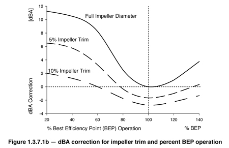
Impeller trim and operating point—Hydraulic noise typically increases with pump operation at flow rates well below or well above the BEP of the pump, or with an increase in the impeller diameter as shown in Figure 1.3.7.1.b. This correction factor is highly dependent on pump specific speed and pump construction. As a result, Figure 1.3.7.1.b should only be used as a guide.
Noise cladding or enclosure—Noise insulation in the form of cladding or enclosure will reduce the noise energy transmitted to the air by the equipment. The supplier of the noise insulation can estimate the appropriate reduction factor. Caution should be taken in the use of cladding or enclosures since these will also provide heat insulation with the net effect of increased air temperature within.
Barrel pumps (double case —The outer case of a barrel pump acts similarly to a noise cladding on the internal pump cartridge. This noise reduction can be estimated at approximately 1.0 dBA.
Refer to ANSI/HI 1.4 Rotodynamic (Centrifugal) Pumps for Manuals Describing Installation, Operation and Maintenance for additional details. Also refer to ANSI/HI 9.1-9.5 Pumps – General Guidelines for details of measurement methods.
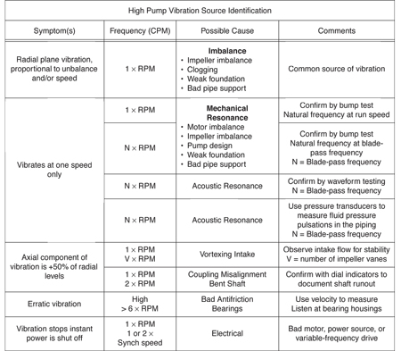
Q. What are the factors that cause excess pump vibration, and how can the specific cause be identified?
A. The factors affecting vibration are:
- Mechanical unbalance of rotating parts
- Mechanical unbalance from abrasive fluids wear
- Pump and driver natural frequency and resonance
- Miscellaneous mechanical problems
- Hydraulic disturbances
- Hydraulic resonance in piping
- Poor structural rigidity
ANSI/HI 9.6.4-Rotodynamic Pumps for Vibration Measurements and Allowable Values contains additional details pertaining to pump vibration.
Pump FAQs® is produced by the Hydraulic Institute as a service to pump users, contractors, distributors, reps and OEMs as a means of ensuring a healthy dialogue on subjects of common technical concern.
HI standards are adopted in the public interest and are designed to help eliminate misunderstandings between the manufacturer, the purchaser and/or the user and to assist the purchaser in selecting and obtaining the proper product for a particular need.
As an ANSI approved standards developing organization, the Hydraulic Institute, process of developing new standards or updating current standards requires balanced input from all members of the pump community.
Pumps & Systems, April 2011
