
The radial forces that form about the periphery of a single volute pump's impeller are proportional to total pump head, impeller diameter and vane width. They are seldom balanced, but they reach their lowest intensity between 80 and 100 percent of BEP flow. The actual low point depends on Pump Specific Speed (Ns) and moves closer to BEP as Ns increases. This unbalanced radial thrust increases quickly as operation moves to the left of BEP and typically reaches its maximum value at shut off head. Radial Thrust intensity is also a function of Ns and increases with an increase in Specific Speed.
Increased shaft deflection is the expected result of an increase in unbalanced radial thrust. Excessive shaft deflection can lead to premature seal, bearing and wear ring damage and failure. In extreme cases it can result in shaft breakage. One of my ongoing concerns is that the H/Q curves published by many pump manufacturers allow operation in questionable areas-some well below 50 percent of BEP flow. This may not be a problem with low Specific Speed pumps that operate at lower flows and heads but, unfortunately, these broad operating ranges are often applied across the board. Increased radial thrust and the accompanying increase in shaft deflection can be especially problematic with higher head wastewater pumps due to the large vane width required to pass solid matter.
The equation below can be used to calculate radial thrust at any point on a pump H/Q curve.
FR = KR x (H x s/2.31) xD2 X b2
Where:
FR = Radial thrust in psi
KR = Radial thrust factor
H = Head in feet at the flow point
s = Specific gravity
D2 = Impeller diameter in inches
b2 = Impeller width at the vane discharge including the shroud(s) in inches
Head and impeller diameter can be found on the performance curve while impeller width must be measured or obtained from the manufacturer. The radial thrust factor can be determined from a graph provided by the Hydraulic Institute (HI). If Pump Specific Speed (Ns) is not known it can be easily calculated from data that is available on the performance curve.
To promote greater use of the radial thrust equation, I developed a simple Radial Thrust Calculator in Excel format. It provides a simple way to calculate radial thrust at any point on the performance curve and identifies pumps that may be susceptible to high radial loading due to off BEP operation. A screen shot of the calculator is shown in Figure 1. It is available for download on my website.
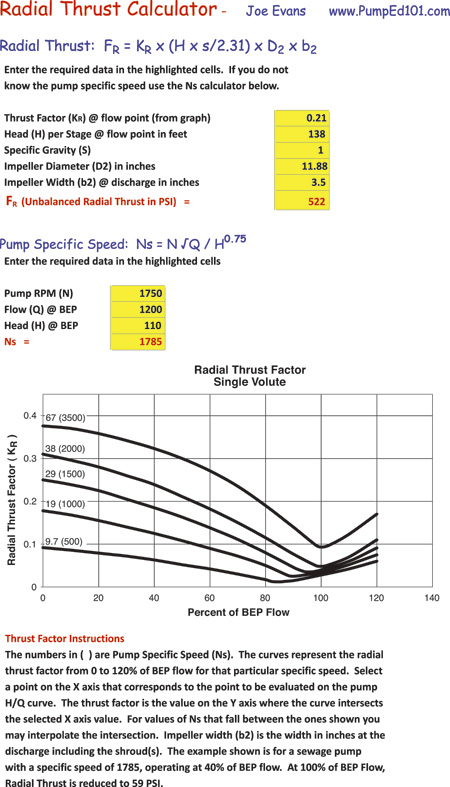
Figure 1
All information that the calculator requires is available on the manufacturer's performance curve with the possible exception of impeller vane width. Pump Specific Speed (Ns) is needed to find the radial thrust factor from the HI graph. If it is not shown on the performance curve, it can be calculated with the Ns calculator shown in the bottom left of the screenshot. Instructions for determining thrust factor are below the graph.
The sample data, shown in Figure 1, are for a sewage pump that has a manufacturer approved operating range of 25 to 137 percent of BEP flow. At a flow of 480 gpm (40 percent of BEP flow) the calculator shows an unbalanced radial thrust of 522 psi. If we recalculate thrust using the BEP flow data shown in the Ns calculator, the results would show an unbalanced radial thrust of just 59 psi at BEP flow. Is this shaft designed to accommodate an increase in radial thrust that is almost eight times larger than that which occurs at BEP? I think that this is a reasonable question to ask the manufacturer.
