Pumps & Systems, March 2013
A few years ago, I took a class to learn to be a horologist—a person who repairs antique mechanical clocks. My instructor said that some of the students may learn to be good clock repair people, but time will tell. That expression started with clock repair.
If a horologist does a quality job repairing a wall clock, it can be wound and will run for eight days before a rewind is needed. If the horologist repaired the clock poorly, the clock might quit after only four days and keep bad time. The device can be rebuilt, but the quality of the time it keeps reflects on the horologist. Do a bad job, and time tells on you.
In a tighter economy, plants and facilities rebuild their own pumps to cut costs. Some plant managers believe that using plant personnel instead sending it out for repair is less expensive. Time will tell with pumps rebuilds, too.
I have participated in the supervision of many electrical and mechanical repairs. If an electrical mistake is made, it is known quickly. The lights go out; sparks fly; or even worse, something melts.
However, mechanical repair mistakes are less obvious. Miss a critical step in alignment, ignore the bearing fit or allow the shaft to wobble, and the pump continues to run. It pumps, but time will tell how long it will last. The unit might only last two years when it should have lasted 10 years. After two years, supervisors may forget who previously serviced the pump, and two years may become the normal expectation. If it stopped working after a week, management may pay more attention. Rebuilding a pump to last requires skill and a focus on detail. This article provides steps to follow when rebuilding a pump to lengthen the time interval between repairs.
Check for Piping Strain
A simple check can be made to avoid piping misalignment and the strain that it puts on critical pump components, such as bearings and mechanical seals. When the pump has been properly shut down with safety locks in place, separate the coupling between the pump and the driver.
Place two dial indicators on the pump coupling half or the pump shaft if it is accessible. A good way to hold them in place is with a magnet base. One indicator is placed on the side of the coupling half to detect horizontal movement. The other is placed at the top to detect vertical movement.
Depress the indicators and set them at zero. Then release the bolts on the suction and discharge flanges. They do not have to be removed, just backed off to be finger tight. If either indicator moves 0.001 inch or more, piping strain exists and must be corrected before re-installing the pump after the rebuild.
This step is often skipped. Chances are the new or rebuilt pump put in the same location with the same piping will have a short life because of the twist and stress induced when the piping is secured.
Inspect Bearing Fits
Installation of anti-friction bearings involves some measurement steps. The bearing is round when it is removed from the box. It has certain prescribed internal clearances that allow for smooth movement. If the shaft is oversized or slightly tapered in the bearing seat or if the housing bore is “belled out,” the bearing will not remain round during operation. Roundness in a bearing means long life.
Check the housing bores and shaft seats with a micrometer capable of reading to ten-thousandth of an inch (0.0001 inch) to ensure proper fit. This step must be completed. If an end user does not know the proper dimensions, they should ask the pump vendor for a “critical dimension checking print,” or look up the proper fit using Machinery Handbook or a similar industrial reference.
Unfortunately, if a machinist fails to make a shaft correctly, he/she will often leave it slightly oversize and the housing bore a bit undersize. Metal is easier to remove than to add back, so they shoot high on the shaft and low on the bore (always leaving metal that can be removed). They sometimes leave more than desired. The pump bearing will install, but it will be pinched on the outside diameter (OD) or expanded too much on the inside diameter (ID) and will fail quickly. Remember, the pump bearing might last a year in this condition, but it should have lasted 10 or more if the dimensions were correct.
Trimming the impeller diameter to give a better performance, even if completed on a lathe, removes unequal amounts of metal from the cast surfaces resulting in dynamic unbalance.
Ensure Pump Shaft Straightness
Pump shafts are subjected to unbalanced impellers, worn bearing fits, impeller rubs and other mechanical strains that can cause them to bow. With the pump shaft removed from the pump during the rebuild and all other components removed, end users should take the opportunity to check the shaft for straightness.
A pool player takes the cue, lays it on the pool table and rolls it back and forth. If it bumps as it rolls, it is not straight. A similar check on a shaft can be completed on a shop bench with a dial indicator and two V-blocks.
Place the shaft bearing seats on the V-blocks and position the indicator at the center of the shaft. Turn the shaft slowly while watching the indicator hand. On a 24-inch pump shaft (or smaller), the indicator should not deflect more than 0.002 inch. In the 24-inch to 60-inch range, 0.003 inch is the limit. For 60-inch to 120-inch pump shafts, the deflection can be to 0.006 inch at the midpoint. If a shaft is bowed in places, an unnecessary push on the bearings and seal faces occurs with each revolution. Seal life is reduced to months instead of years.
Carefully Heat the Bearing for Shaft Installation
Almost all pump bearings have an interference fit between the ID of the bearing (the bore of the inner race) and the shaft seat (the place where the bearing sits on the shaft). The bearing bore is smaller than the pump shaft and must be pressed on or heated to expand the bore before assembly. An anti-friction bearing is a great example of metallurgy. The bearing companies use excellent quality control to produce a bearing that is hard, but not too hard, to provide a long service life. If the bearing is overheated, it becomes annealed and will not last for its intended life.
Modern shops use induction heaters or cone heaters to rapidly heat the inner race to allow shaft assembly. However, the temperature-sensing mechanism on the heater can often be out of calibration or non-existent. In that case, the mechanic must use an infrared thermometer or temperature sensitive crayon that melts at the correct temperature value to make sure that the bearing is not overheated.
The magic number to avoid is more than 250 F. Most good pump shops never heat them to more than 230 F to avoid the possibility that they will overheat the bearings. Overheating a bearing during assembly removes years from its life, and plant management may never know the true reason for the shortened life cycle.
Square the Bearing to the Shaft Shoulder
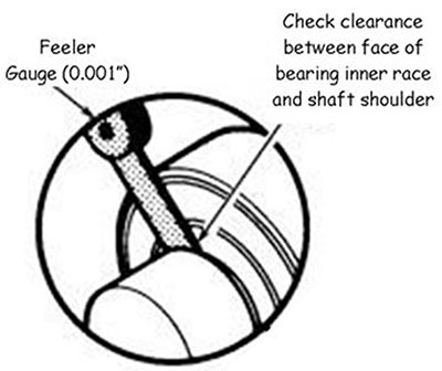
Improper squareness causes frequent problems. All pump shafts have a shoulder that determines the stopping point for a bearing on the shaft. The face of the inner race of a bearing should meet this shoulder all around the shaft—it makes the bearing square to the shaft (at a perfect right angle).
Pump manuals caution, “Make sure the bearing is square.” However, many do not indicate how. The check is an easy one. A feeler gauge of 0.001 inch to 0.002 inch is used to see if any gap exists between the face of the inner race and the shaft shoulder at the 12, 3, 6 and 9 o’clock positions.
When using a press to install a bearing, a gap is usually not present, or less chance exists of one. If thermal means are used to expand the inner race (no more than 230 F), the bearing must be held against the shaft shoulder so it does not shrink away as it cools. Most mechanics may think that holding the bearing in place for a minute or two will be enough to avoid a gap. This line of thinking is incorrect. The bearing should be held in position for 3 to 5 minutes. This simple step, if not performed, leads to cocked bearings and rapid bearing wear following installation.
If the bearing is not square to the shaft shoulder, bearing misalignment occurs. Checking squareness is vital to ensure that a pump spins freely.
Rebalance a Trimmed Impeller
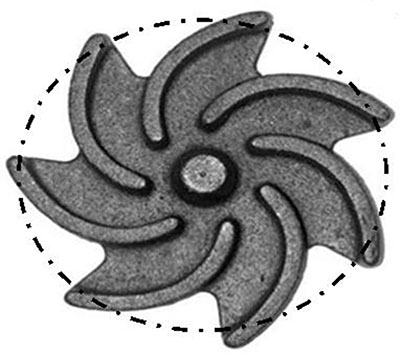
With emphasis on energy savings and a desire to operate a pump closer to its best efficiency point (BEP), the impeller’s diameter is often trimmed to ensure that the pump more closely fits the system’s requirements. The affinity laws are used to calculate that, for instance, a 10-inch diameter impeller should be machined down to 9½ inches to better marry the pump curve to the piping. If an end user orders a 9½-inch diameter impeller from the factory, it is dynamically balanced.
However, if a machine shop trims the impeller in a lathe, the impeller is unbalanced. It is a casting. The removal of as little as ¼ inch from the diameter can result in massive unbalance when the pump spins at 1,750 rpm or worse at 3,550 rpm.
Asking the machine shop to send the impeller out for dynamic balancing is no trouble and costs little, certainly less than the failed bearings and unplanned downtime that can occur as the pump vibrates because of unbalance. When the pump is assembled, that is not the time to think about balance.
Balancing must take place during disassembly. The components can be placed on a balancing machine and corrected before reassembly. In some cases, the shaft and impeller should be assembled together and balanced as a unit to ensure against excessive vibration forces. P&S