The term “total head” (H) is used to describe the energy in pumping systems and is how manufacturers represent the performance of their pumps as a function of flow rate. Total head is also commonly referred to as total dynamic head (TDH); however, the Hydraulic Institute (HI) uses the term total head and it will be used throughout this article.
It is important to understand the nuances of what makes up the total head of the system as a function of flow rate and varying system conditions so that if a user is designing or operating a pump system, the pump can be selected and operated properly. Additionally, if the goal is to measure the pump performance after installation, it is important to understand how to do that in the same way that the pump manufacturer will.
Total head (system) is made up of three components:
Elevation head, which is the difference in elevation that liquid will travel. For example, if a user was pumping from one tank to another and the level in the tanks were the same, there would be zero elevation head. But if pumping from a tank at ground level to the roof of a 100-foot building, there would be 100 feet of elevation head.
Pressure head is the difference in pressure between source and destination. For example, if taking liquid from a lake at atmospheric pressure and delivering it to a tank that had 10 pounds per square inch (psi) above atmospheric pressure, the pressure head would be 10 psi expressed as feet of the liquid being pumped. The conversion between pressure and head is described in the pump total head measurement section.
Friction head is the head loss in the system due to friction and is a function of the liquids velocity or flow rate squared. As mentioned, the friction loss will depend on the flow rate but also the size of the piping, fittings, valves and end use equipment in the system. If there are control valves in the system that are used to actively regulate the flow rate, the friction loss across the control valve is referred to as control head. It is important to understand control head because it is often a source of energy consumption that can be improved.
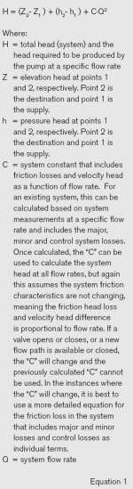
A free resource that provides additional tutorial information on this topic and includes a friction loss calculator is the Hydraulic Institute’s Engineering Data Library, which can be accessed at edl.pumps.org. For complex systems with many pieces of equipment and branches, it may be difficult to calculate the total head for the system by hand and hydraulic modeling software should be used. Some noncommercial versions of hydraulic modeling software are available as a free resource at pumps.org/freetools. A simplified equation for total head (system) is expressed in Equation 1 (page 100).
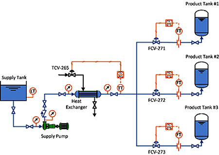
Image 1 shows a pump system where liquid is delivered from a supply tank to three closed product tanks. Considering the equation for total head (system), the supply tank would be point 1 and the product tanks would be point 2. The elevation head would be the difference in elevation between the level in the product tank and the supply tank. The pressure head would be the pressure difference between the product tank and the supply tank expressed as feet of the liquid pumped. Friction head would include all of the losses from the supply tank, piping, fittings, heat exchanger, control valves, etc.
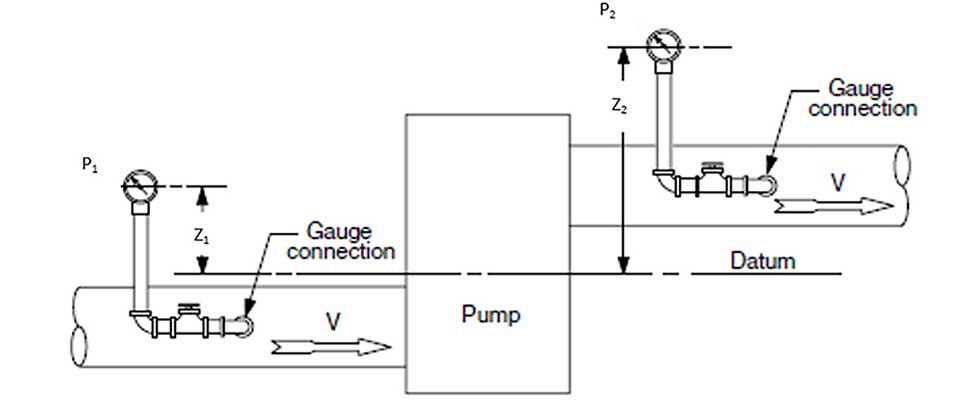
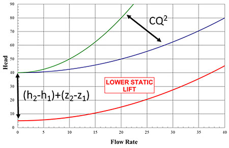
Image 2 shows how the system head will change as a function of the equation variables. In the case of the elevation and pressure heads, the total head (system) curve will move vertically up and down as these variables change. In the case of friction head, it will change as a squared function of flow rate, and the “C” coefficient expressed in the total head equation will change based on the flow control valves (FCV-271, FCV-272 and FCV-273). As the flow control valves open, the “C” coefficient would decrease and total head would decrease, and conversely, as the flow control valves close, the “C” coefficient would increase and total head would increase.
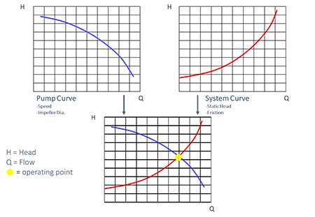
The total head (pump) will match the total head (system) at a specific flow rate. This means, when plotted on the same graph, where the pump curve and system curve intersect will be the pump’s operating point. Image 3 shows how these curves are combined and that the resulting intersection is the operating point.
The pump curve or total head of the pump as a function of flow rate is measured much like the total head of the system but points 1 and 2 will be on the inlet and outlet of the pump, respectively. Image 4 shows pump pressure instruments referenced to a common datum and the direction of flow is indicated by arrows. The total head of the pump is the difference between the total discharge head (point 2) and the total suction head (point 1). The term “total” indicates that it includes the static pressure head (h), the velocity head (hv), and the elevation head (Z).
The equation for total head (pump) can be expressed in Equation 2.
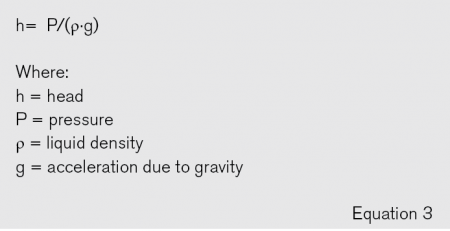
To measure the total head of the pump, pressure will be measured at points 1 and 2, the elevation from the pressure gauge to datum will be measured, and the velocity at the pressure measurement location will be calculated based on the volumetric flow rate and the pipe inside diameter. The pressure measured will need to be converted to feet of liquid based on Equation 3.
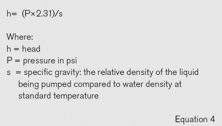
When doing the calculation, attention will need to be paid to units to get the calculation to come out correctly. With U.S. customary units, it is common to use a relative density called specific gravity and a conversion constant to convert pressure to feet. This can be done using Equation 4.
Total head is a fundamental that is beneficial to understand when working with pumping systems. It provides an understanding of the system requirements, valuable information for pump selection, and a key consideration of energy consumption. This article covers the basics but does not discuss in-depth review, calculation examples or scenarios that pump professionals will come across. For more information on this topic, including standards and training, visit www.pumps.org.