Plus the Top 4 anomalies to look for when performing a field inspection.
Garlock Sealing Technologies

Control unit installed
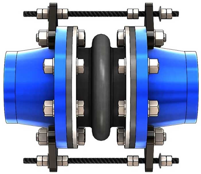
Image 1. Control unit installed (Images courtesy of the author)

It is no secret that one of the greatest demands for an expansion joint is the expectation to serve a long, leak-free life with little to no maintenance. Once installed, these flexible rubber connectors should require little attention. The preservation of this investment (and one’s sanity) can be maximized with an in-depth overview of how control units can prevent a new expansion joint from being overstressed.

The purpose of a control unit is to act as a safety device against excessive movement resulting from pressure thrust. A typical control unit assembly is comprised of threaded rods, steel gusset plates, nuts and washers (see Images 1 and 2).

Typical control rod assembly components
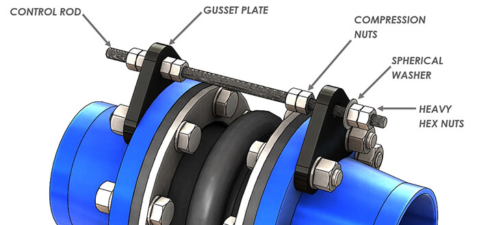
Image 2. Typical control rod assembly components

The usage of control units with an expansion joint is always beneficial; pressure spikes during a system upset can cause uncontrolled surges through the expansion joint. This is a prime example of how valuable it is to have control units installed to protect these rubber assets from damage.

Methods to the Madness

A common misconception about control units is that they are designed to support the weight of pipe members or act as a substitute for adequate mounting. They are not. The sole purpose of a control unit is to allow the expansion joint to move freely within a specific range of movement while preventing the joint from being overstretched from pressure thrust forces.

Effects of pressure thrust
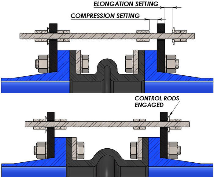
Image 3. Effects of pressure thrust

The control units in no way impede the joint from performing its other duties beyond movement (vibration absorption, cycling or compensation for misalignment). The few extra steps needed to install the control units with the expansion joint could pay notable dividends in the long run.

Pressure thrust plays a huge role in how an expansion joint functions. While under pressure, the forces acting on the inside walls of the expansion joint actually cause the joint to swell and elongate. In the real world, an expansion joint is held comfortably between two pipe flanges, which in most cases are restrained by a pump lagged to the floor or mounted to a structural beam. Although it may not be apparent to the naked eye, once the expansion joint sees pressure, it produces a thrust force that acts axially on both pipe flanges.

Theoretically, what would be the result if the expansion joint was unrestrained on each end while pressurized?

Without fixed ends, the pressure thrust would force the joint to elongate without bounds.

Most useful in high pressure applications, the control rods will engage with the gusset plates once a prespecified amount of growth for the expansion joint has been reached, restricting the joint from stretching any further. At this point, the control rods are absorbing any additional thrust acting on the pipe flange, thus limiting the amount of stress that is exerted onto adjoining equipment.

The design theory for sizing control unit hardware is based on the pressure thrust. Nominal inside diameter (ID) and arch geometry of the expansion joint are key drivers for calculating the thrust force that will be applied to the pipe at maximum line pressure. Per industry standards set by the Fluid Sealing Association (FSA), both control rods and gusset plates are designed to withstand no more than 65 percent of the yield strength of the material.

Arch diameter D
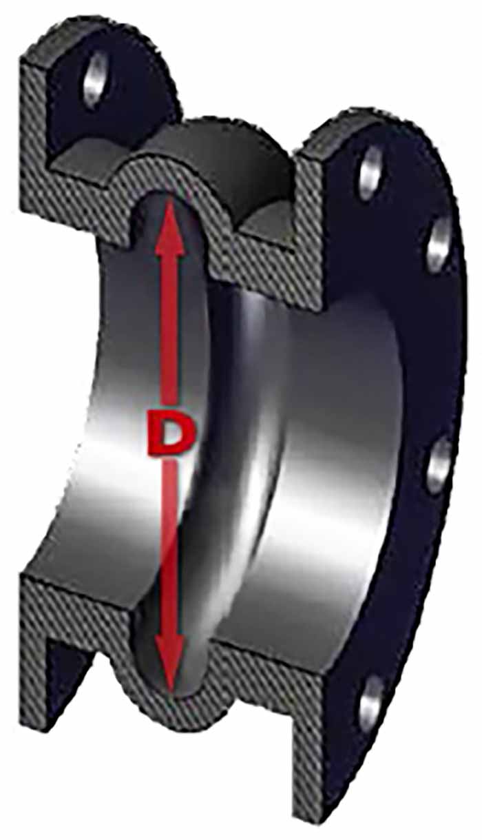
Image 4. Arch diameter “D”

Magnitude of the pressure thrust can be calculated by knowing the internal pressure and the effective area of the expansion joint. Effective area is found using the arch diameter of the expansion joint, which takes into account the size of the arch.

For example, we can calculate the resulting pressure thrust for a 10-inch ID expansion joint using an arch height of 1.5 inches that is rated for a maximum pressure of 250 pounds per square inch (psi).

The equation for pressure thrust “T” is:

Equation 1

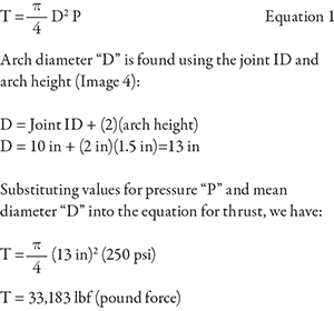
These design limitations based around yield stress are the reasons why some control units made from lower yield strength stainless steel contain thicker components or more rods per set than the standard carbon steel control units.

Installation & Inspection

For a control unit assembly to be effective, rod positioning and elongation settings are critical during installation. Each control rod should be evenly spaced around the flange to best distribute the load. Elongation settings (see Image 5) are often overlooked, yet are a vital factor to ensure the control units fulfill their intended use.

Every expansion joint comes with movement ratings based on arch size, configuration and number. These movement design ratings of the expansion joint are critical pieces of information that are absolutely required during the installation of control units. The general rule of thumb is the gap between the gusset plate and the nut should be adjusted to match the joint’s elongation rating.

Having this information at hand during installation is great, but what about the existing control units currently in operation? Visual inspections of these components are a basic task that goes a long way toward extending the life of the joint.

Here are the top 4 anomalies to look for when performing a field inspection:

Measuring elongation settin
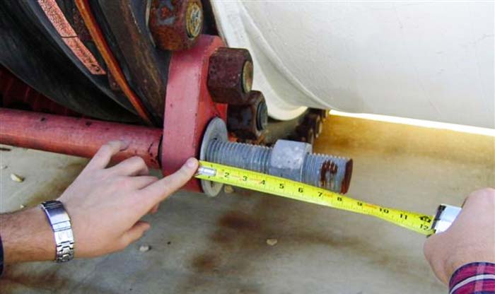
Image 5. Measuring elongation setting

Elongation Gap Setting
If the gap setting is larger than the elongation rating of the expansion joint, the joint could be stretched beyond its limits, and damage could occur to the joint in the form of cracking around the base of the arch and/or flanges (see Image 5).

Control units can be adjusted at any time, and it is not too late to make corrections in the field. In addition to adjustments made to the nuts, the gusset plate along with the entire rod assembly can be relocated for better spacing without breaking the seal between the rubber joint and pipe flange.

Locked out control rod
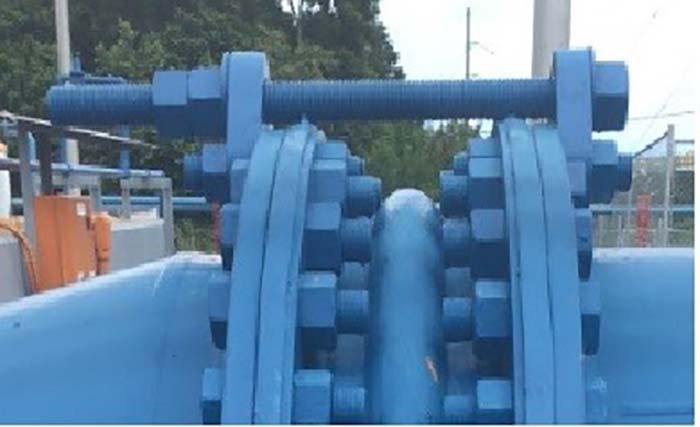
Image 6. Locked out control rod

Locked Out Control Rods
For unrestrained piping systems, intentional tightening of the control unit nuts is preferred by equipment manufacturers and pipe engineers. Applications where an expansion joint is leading into a condenser would benefit from locked out control units where the resulting pressure thrust forces would be restrained and eliminate transferring stress to the equipment. Since it is not desirable to have the expansion joint moving in multiple directions at once, locking the joint in its nominal face-to-face length will prevent elongation while still allowing the joint to compensate for any lateral movement (see Image 6).

Restrained piping systems are treated differently, where the pipe mounts are designed to take on the resulting stresses of pressure thrust. Accounting for the elongation gap setting during installation will allow the expansion joint to grow and relieve the pipeline from thermal stresses. In this case, locking control units could result in higher stress being taken by the pipe rather than being absorbed by the expansion joint.

Control rod interference
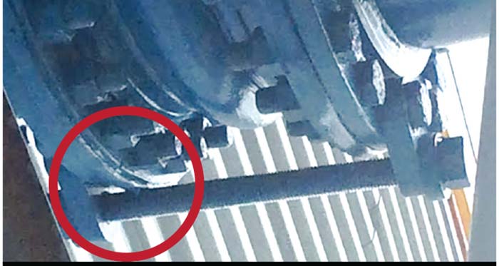
Image 7. Control rod interference

Control Rod Interference
Interference between the control rod and the outside diameter of the pipe flange can also be detrimental to the performance of the control unit assembly (see Image 7). Interference can typically be found on expansion joints with excessive lateral offset, tapered reducing joints or a control unit assembly not specified to the correct application. Typically an alternate gusset plate design is the solution to this problem.

Gusset plate exceeding yield
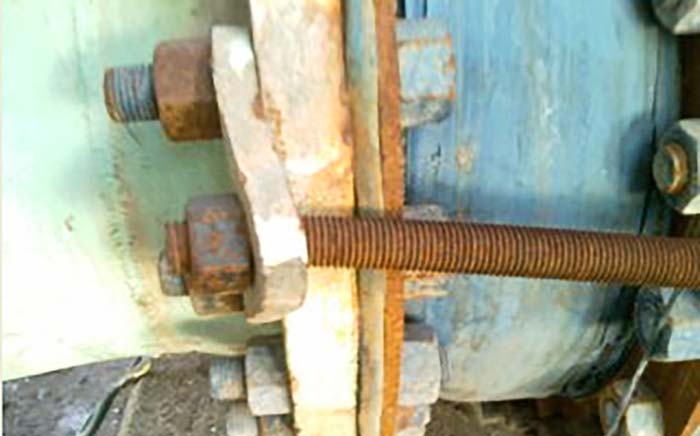
Image 8. Gusset plate exceeding yield

General Condition
This may be obvious, but a quick inspection for overall condition of the control unit components is beneficial in determining if replacements are necessary or if bigger problems are underlying. Extremely corroded hardware could mean a switch to zinc plated or stainless steel is warranted. Distorted control rods and/or gusset plates might require a redesign that would provide better reliability for the application (see Image 8).

Ensuring the correct control unit setup is an important step toward the preservation of the expansion joint. The condition of control units can be easily monitored, and corrections to setup can be made during downtime.
If there is concern of risk to an expansion joint in service, control units can be added at any time by consulting an expansion joint provider.

References
Expansion Joints – Piping Technical Handbook, 8.0 edition. Fluid Sealing Association (2016).

Next Month: Unusual mechanical seal applications

We invite your suggestions for article topics as well as questions on sealing issues so we can better respond to the needs of the industry. Please direct your suggestions and questions to sealingsensequestions@fluidsealing.com.

Read more Sealing Sense articles by clicking here.