

Machinery vibration analysis is a commonly used technique to locate and identify problems in centrifugal pumps. Problems such as cavitation, restricted discharge, balance, bearing and alignment condition and a handful of other issues are well-recognized faults analyzed using vibration signature analysis. Machinery vibration is nothing more than repetitive movement of a part around a midpoint or point of rest. This motion is measured by placing a vibration sensor mounted on respective motor and pump bearings to convert this motion into an electrical signal that represents amount and frequency of motion of the bearing at the location and direction the sensor is mounted. These electrical signals then undergo a fast Fourier transform (FFT) to find amplitude and frequencies of the forces that create this unwanted, and usually destructive, motion.
Fault frequency charts have been developed to determine the source of force, and amplitude of the motion determines the amount of the force. As successful as this technology has been, it faces some limitations and obstacles. Among those are Newton’s 2nd law, (force = mass X acceleration). This means that as the applied force increases, the motion (acceleration) will increase, or if the force is constant and the mass is increased, the vibration will decrease. This means that on larger machines, more mass requires more force or a more advanced fault to create a given vibration. So, on larger machines, by the time a fault is large enough to create measurable motion, the fault is advanced.
Additionally, vibration sensors are directional and only measure motion in the direction and plane of sensor orientation. This means that a fault that is directly under the transducer may be missed. This is a common problem with vertical pumps or other hard-to-access locations.
Motor Current
In limited access situations, current clamps have been used as the transducer to measure these same forces. The same forces that cause the machine’s casing to vibrate also cause the motor’s load to increase and decrease, which causes the motor’s current to modulate at the same frequencies. For example, if an unbalance force causes the motor bearing to vibrate at one times rotor speed, it will also cause the motor current to “modulate” at the same one times running speed. The electrical output of the current clamps then undergoes FFT to determine the amplitude and frequency of these forces. Any other repetitive periodic forces that create the unwanted and destructive motion at the bearings also cause the motor current to modulate at the same frequencies as the motion. Forces that randomly occur such as cavitation will create a broadband spectral response—the same as in a vibration spectrum.
When inputting the electrical signals from the output of the current clamps into an FFT, it is possible to find the amplitude and frequencies of these forces and they will be the same as the frequencies presented in the standard vibration charts. This technique is referred to as motor current signature analysis (MCSA).
Some users incorrectly presume that MCSA can only be used to identify faults in the motor itself. However, since all power to the motor system comes through the motor, the motor current makes a transducer to identify any cyclic forces and random forces that are applied to the bearings or other parts of the pump system that create the vibration.
In addition to electrical and mechanical faults in the motor, any periodic or random occurring forces in the pump/motor system will create modulations of the motor current and can be identified from the motor currents.
This allows the motor current to become a powerful tool when troubleshooting mechanical, electrical and even hydraulic problems in a pumping system being driven by electric motors. In addition to identifying all of the problems that machinery vibration detects, MCSA is not restricted by sensor location, direction or frequency response.
EPRI Study Vertical Pumps
An Electric Power Research Institute (EPRI) report in the mid-1980s showed that faults located in the subsurface section of vertical pumps are undetectable using vibration sensors mounted on the motor bearings located above the surface. However, these faults are easily detectable using the motor current as the transducer. Faults such as resonant whirl, looseness, restricted discharge and cavitation can be easily identified in the current signature. Even common faults such as unbalance of the pump rotor dangling from the motor shaft fail to cause the motor to shake until all the pump interstage bearings or bushings are destroyed.
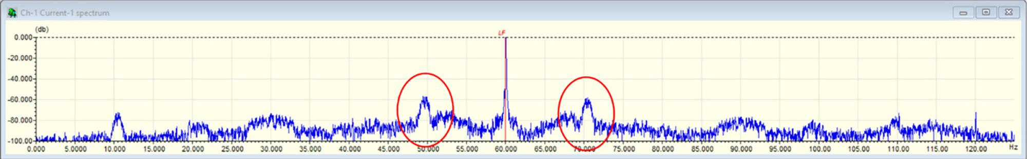
Image 1 is the motor current from one of the two vertical cooling water pumps that were exhibiting poor performance under certain conditions. Two other identical pumps did not exhibit performance issues. Several diagnostic tests were conducted including vibration, pressure, flow and electrical signature analysis (ESA).
On the two pumps that were exhibiting performance issues, both displayed this flow turbulence under certain pump configurations and water levels in the lake supplying the water. It was surprising to the maintenance team that ESA was the only technology that exhibited this condition. Using this information, the plant was able to determine proper pump combinations that would prevent these conditions from occurring.
ESA vs. MCSA
The above benefits of using the motor current as a transducer can be readily seen for early fault detection of mechanical, electrical and hydraulic faults and analysis as well as identifying faults in inaccessible locations on pump systems driven by induction motors. ESA differs considerably from MCSA, which is simply an FFT on one or more phases of the motor’s incoming current. The disturbances that are displayed in the motor’s current spectrum can be caused by any periodic loading applied to the motor bearings.
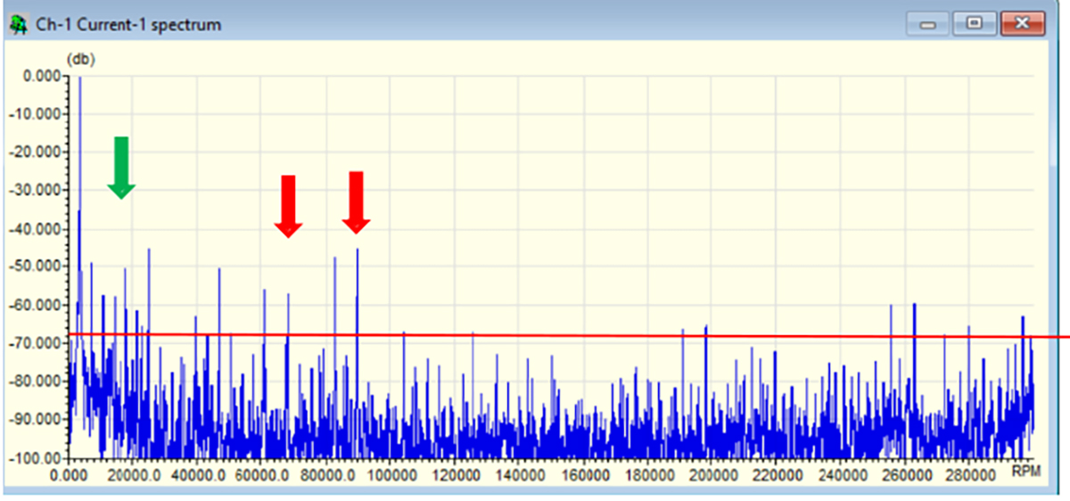
Forces caused by unbalance, misalignment or any other anomalies in the rotating portion of the pump system will cause the motor’s current to modulate at specific frequencies of the periodic force based on rotor speed, pump and system design. This could also be caused by harmonics or other disturbances in the supply voltage directly from the utility or any electrical disturbances created in the plant’s internal electrical distribution system. Disturbances from the pump’s flow or other hydraulic forces within the process can also contribute to the current spectrum. This makes it seem difficult to interpret and analyze the FFTs. In the current spectrum (Image 2), there are several spectral peaks, some of which exceed -60 decibels (dB). This indicates that the disturbance creating the spectral peak is greater than 1/1000th of the motor’s current.
However, by comparing the current spectrum with the spectrum of the incoming voltage, it becomes apparent that most of these peaks are the result of disturbances of the incoming voltage and are not related to the condition of the motor, driven machine or the process. This allows the analyst to focus only on the faults that are related to the condition of the motor system and eliminate any disturbances that are caused by the incoming power. It is also important to note that some of the spectral peaks (peaks under purple arrows) in the voltage spectrum are not present in the current spectrum. This is because the stator windings act as current filters and can filter out some of the disturbances contained in the incoming voltage. In Image 2 and the top image, note that the peaks under the red arrows are present in both the voltage and current spectrum, which means the peaks under the green arrows are present only in the current spectrum. This means they are being caused by faults in the motor, pump or the process.
Power Quality
In addition to performing an FFT on the motor current and voltage, ESA also performs a simultaneous data capture on all three phases of voltage and current to create a power quality (PQ) table. It also captures a snapshot of the voltage and current time waveforms.
The PQ table displays all the key variables necessary to evaluate the condition of the incoming power, motor load and efficiency. This provides a more accurate and complete depiction of the motor’s electrical condition, as well as the quality of incoming power.
ESA also can accurately calculate the actual motor speed at the time of the motor test. Since ESA performs a simultaneous data capture of all three phases of voltage and current, it is a simple mathematical calculation to accurately determine running speed of the collected test data set. This greatly improves the accuracy of FFT analysis.
The use of ESA is increasing on pumps driven by electric motors due to its ability to evaluate the entire pump system, incoming power and process quickly in a one-minute test. Just as with other diagnostic technologies, the horizon, knowledge base and capabilities of ESA are in the early stages, so more benefits and additional uses of this technology are also in their infancy.
Problems Identified by Using ESA:
Power Quality
- power factor
- voltage and current unbalance
- motor load and efficiency
- voltage and current
- harmonic content
- torque fluctuations
- motor stator
- air gaps
- winding/core looseness
- insulation breakdown
- groundwall/winding
- rolling element bearing condition
Motor Rotor
- unbalance
- misalignment
- eccentric rotor
- loose/broken rotor bars
- casting voids
- thermally sensitive rotors
Pumps
- unbalance
- misalignment
- recirculation
- restricted discharge
- cavitation/flow disturbances
