
In recent years, pump professionals—including engineers, operators and plant managers—have come to assume that variable speed drive is synonymous with variable frequency drive (VFD). Even in technical journals with no marketing purpose, the two terms have been used interchangeably, which might lead one to believe that VFDs offer the only viable solution to achieve variable speed operation. The ability to adjust pump speed to match varying demand has long been preferred to operating pumps at full speed and throttling the discharge or bypassing excess flow back to the intake. Adjusting the speed of the pump allows users to take advantage of the affinity laws for centrifugal pumps, resulting in reduced energy consumption. Because power is reduced in proportion to the third power of speed reduction, a relatively small decrease in speed affords a significant savings in power.
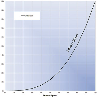 Figure 1. Pump affinity laws: Brake horsepower decreases in proportion to the third power of speed reduction. (Images and graphics courtesy of DSI/Dynamatic)
VFD Predecessors
Before the development and commercialization of VFDs, which began in the 1970s, several technologies were in widespread use for variable speed pumping in water and wastewater applications.- Wound rotor induction motors, with secondary (rotor) resistance control. With this system, the motor speed is controlled using a liquid rheostat system or a series of switched values of large resistors connected to the motor rotor circuit.
- Hydroviscous or oil shear type clutches. These are driven at constant speed by a suitable electric motor and produce a controlled variable speed output.
- Adjustable-pitch belt drives. These simple units include a constant speed motor and a pair of V-belt sheaves that can change effective diameter. They are usually applied in small horsepower applications requiring infrequent changes in speed. They are adjusted manually, but automated remote adjustment systems are available.
- Eddy current drives, also known as eddy current clutches or magnetic drives. These machines are driven at full speed by a standard induction motor and employ a variable strength magnetic field to control torque and speed to the driven load.
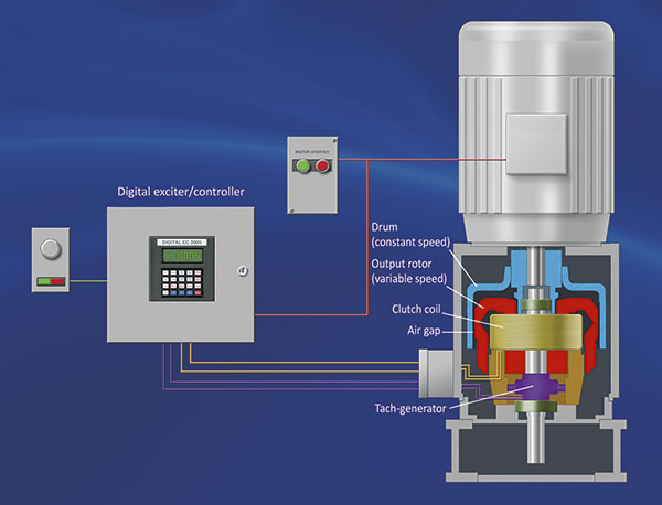 Figure 2. Typical eddy current drive system, depicting internal components
Eddy Current Drives
As seen in Figure 2, the constant speed motor is coupled to an open-ended cylinder constructed of high-permeability magnetic steel, called the drum, which is shown in blue. The drum rotates at the same constant speed as the motor. The motor speed and horsepower are chosen to be equal to or just higher than the maximum required by the pump conditions. A second rotor called the magnet, shown in red, is positioned concentric within the inside diameter of the drum and rotates independently of the drum. An air gap between the magnet and the drum is maintained by antifriction bearings. This magnet member consists of a series of magnetic poles around the periphery of the rotor, wound with a wire coil or, in some cases, individual pole coils. The coil, shown in gold, is energized by a variable direct current (DC) from the exciter/controller. This excitation current establishes alternating north and south magnetization in the pole pieces, which in turn results in a torque transmitted from the drum to the magnet across the air gap. The air gap torque is varied by controlling the DC excitation current. A tachometer-generator, shown in purple, on the output shaft provides a feedback loop to the controller, enabling the system to maintain speed control in real time to a precision of less than 0.5 percent error. The output speed is controlled from near-zero speed to about 98 percent of motor speed. At max speed, a minimal amount of slip is necessary to maintain output torque. The power delivered to the pump is provided without electronic conversion. It is transferred directly from the utility power supply to the motor. The controller operates at about 1 percent or less of the rated power of the drive system. Thus, the controller does not power the output but only serves to regulate the amount of torque transmitted from the motor to the load.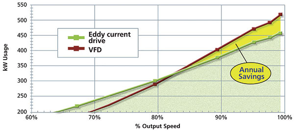 Figure 3. Results of a field study comparing energy consumption of eddy current and variable frequency drives in identical applications. Eddy current drives equal or exceed the performance of VFDs for most of the useful speed range.
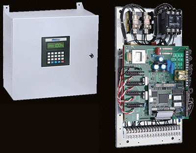 Image 1. Typical eddy current drive excitation controller in wall mount enclosure, showing digital keypad for programming and operator control. Eddy current drives rated up to several thousand horsepower require only a 36-inch x 48-inch enclosure.
- Harmonic distortion on the feeder system, resulting in failures or protective trips of unrelated equipment. In some applications, this distortion appears when the pumps must operate on standby generator systems and has been known to cause malfunction of the generator governor or voltage regulator. It usually results in a diminished capacity for the generator.
- VFD reliability problems due to poor plant power quality such as unstable voltage, voltage imbalance or voltage surges due to lightning or utility bus transfer switching.
- Difficulty in locating the VFD due to large cabinet size or auxiliary equipment such as harmonic filters, reactors or isolation transformers. In some cases, owners have had to add on to existing buildings to accommodate this equipment.
- The need to air-condition the space that houses the VFD to dissipate the VFD losses. This requirement adds to system first cost, increases energy consumption and diminishes reliability.
- Additional motor losses caused by nonlinear output waveform, which diminishes system efficiency.
- Motor bearing failures, attributed to high-frequency shaft voltages that are induced by pulse-width-modulated VFD waveforms. Discharging these voltages to ground through the motor bearings often leads to fluting of the bearing race, resulting in early failure.
- Motor winding failures caused by common mode voltage at the motor neutral. This is most commonly found in applications involving medium-voltage motors that were not specifically designed for this duty.
- Severe high-frequency audible motor noise. While this phenomenon is not known to cause damage to the motor, it is usually disruptive to personnel who work nearby. Some users have gone so far as to build sound enclosures around motors to minimize the disturbance. In some cases, VFDs have been taken out of service or avoided altogether for this reason alone.
- Early obsolescence of VFDs caused by advancing technology or competitive pressure. This problem leads to high repair costs or even unavailable repair parts, frequently resulting in replacement of the VFD within seven to 10 years.
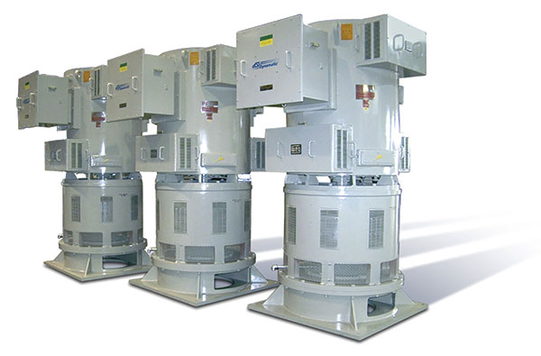 Image 2. A trio of 400-HP, 600-rpm eddy current drives and motors in service at a Midwest wastewater treatment plant. These units replaced motors and VFDs that had suffered several rounds of failure and replacement.