

The vertical design is ideal for sump pump applications and accommodates multiple stages to develop high head when needed. The alignment of the driver to the pump presents some challenges that are beyond those of horizontally mounted machines. Typically, these pumps are driven by a vertical electric motor or by a right-angle gear case connected to a horizontal internal combustion engine. The concentric mounting flanges present a very different situation than the typical mounting feet on horizontal machines. Further, it is very common for the pump rotor to be supported vertically on the motor shaft with a rigid coupling, so the pump rotor cannot be rotated when the coupling is disconnected.
Alignment Challenges
Rigid couplings
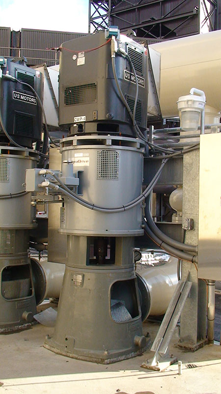
Most vertical turbine pumps (VTPs) have the rotor supported by the motor (no axial support in the pump bearings), so a rigid coupling is used between the motor shaft and the pump shaft (Image 1). For most VTPs, the shaft extension is properly called a line shaft, but “pump shaft” will be used here for simplicity. Misalignment between the two shafts is accommodated by flexure of the coupling components and the shafts themselves. While typical flexible couplings can accommodate significant misalignment, these rigid couplings cannot. Proper shaft alignment is critical for these machines.
Concentric flange mountings
Theoretically, the concentric flange mountings on the pump and the driver would eliminate the need for alignment adjustment. If the pump flange was perfectly concentric and perpendicular to the pump shaft, and likewise for the motor flange and shaft, the alignment between them would also be perfect. Of course, this is not the case. Motor manufacturers conform to National Electrical Manufacturers Association (NEMA) or International Electrotechnical Commission (IEC) standards for allowable runout of motor flanges. The tolerance for concentricity and face runout is 0.003-0.012 inches for NEMA and 80-200 micrometers (µm) for IEC, depending on flange type and size. For machines in service subject to wear and distortion, greater runout may be encountered.
There are no industry standards for runout of the pump flange; significant concentricity and face runout may be encountered. So while the theoretical flange design eliminates the need for shaft alignment adjustment, the practical situation demands that alignment be assessed, and adjustment is commonly required to achieve satisfactory operation. Tolerances for VTP shaft alignment are provided in the American National Standards Institute/American Standards Association (ANSI/ASA) S2.75-2021 Shaft Alignment Methodology, Part 3, standard. The standard includes several informative annexes that elaborate on some of the concerns presented here.
Alignment Considerations
Offset alignment
The concentric flange design lends itself to an offset-angularity approach to shaft alignment. Again, theoretically, offset alignment is affected by concentricity of the two mating flanges, and angularity is affected by the face runout of those two surfaces. The serious dilemma is that there is no inherent adjustment in the flange design for either offset or angularity. To the extent that there is clearance in the rabbet fit (or if there is no rabbet fit, as in some P-flange designs), offset adjustment can be made simply by moving the driver in the horizontal plane to center the shafts. Of course, if sufficient clearance exists, there is nothing to hold the driver in that horizontal position. Taper pins or similar methods are commonly used to lock the horizontal (offset) position of the machines.
Angular alignment and shimming
If face runout is such that there is excessive angular misalignment between the shafts, careful consideration must be made about how to correct that angular misalignment, or if that misalignment should be corrected.
What seems to be an obvious solution is to shim between the faces at each bolt location to correct the angular misalignment. However, vibration resonance is a very common problem on VTPs. All VTPs have a reed mode natural frequency; often there are two, one in line with the pump discharge and one perpendicular to it. Shimming between the pump and driver faces will reduce the stiffness of the structure, lowering that reed mode natural frequency. If the natural frequency is changed and happens to coincide with an exciting force, typically shaft rotating speed frequency and harmonics 1xRPM or 2xRPM, resonance and severe vibration will occur. If a machine is known to operate above the natural frequencies, then shimming is unlikely to result in a resonance problem. If the machine is known to operate below the natural frequencies, shimming is a risky proposition. If the natural frequencies are not known, shimming is also risky. An assessment of a machine’s reed mode natural frequencies can be done by a simple bump test.
Alignment Strategy
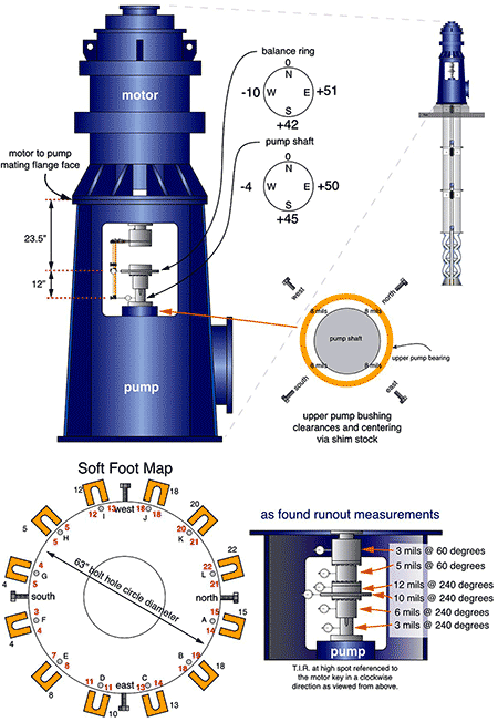
If the decision is made to shim the driver to correct angular misalignment, keep in mind that doing so will change the offset alignment. The order of events should be to correct angular misalignment first and then adjust offset misalignment. Image 2 illustrates some of the measurement techniques and associated data for VTP alignment.
As stated earlier, a decision could be made not to adjust for angular misalignment. It was also mentioned that the flange rabbet fit may not allow for offset adjustment. With these concerns in mind, consider that offset alignment between the shafts results in much more stress on the shafts than would a similar amount of angular misalignment. Unlike flexible couplings, rigid couplings have no means of accommodating offset that occurs across the very short distance between the shaft ends. Angular misalignment is distributed across the distance between the upper pump bearing and the lower driver bearing.
In fact, if shimming can be used, but offset adjustment cannot be made because there is not clearance in the rabbet fit, it may be advantageous to use shims to adjust the angularity for better offset alignment even if it results in greater angular misalignment.
When Proper Alignment Is Not Possible
Obviously, there are situations where it is not possible to achieve proper alignment for both offset and angular measurements. The problem in these cases is the flanges have excessive concentric and/or face runout. The solution is to identify the excessive runout and remachine the offending surface. This is an expensive and time-consuming repair. Facilities that are serious about machine reliability, of which shaft alignment is an important component, address this issue when specifying machines for purchase or for repair.
Measurement Difficulties
In addition to these concerns for assessing and adjusting VTP shaft alignment, there are problems with measuring the actual shaft alignment on VTPs. Since the pump shaft is supported by the driver, it cannot be rotated when the shafts are disconnected. Proper shaft alignment procedures require that both shafts be rotated. If the pump shaft cannot be rotated independent of the driver, it is not possible to measure pump shaft runout. If there is pump shaft runout and the driver is aligned to that pump shaft, the alignment is off by the amount of pump shaft runout. Given the long, slender dimension of VTP shafting, shaft runout is common.
An issue is the clearance in pump shaft bearings, which can be significant relative to proper shaft alignment tolerances. Some practitioners address these issues with specially built tooling to support the pump shaft and center it in the bearing. Such tooling is not standardized or commercially available, but a description of some methods is included in the annexes of the ANSI/ASA S2.75-2021 Shaft Alignment Methodology, Part 3, standard. VTP shaft alignment is much different than standard horizontal machines. If flanges are true and shafts are straight, it is an easy task. If ideal conditions are absent, consideration of the concerns discussed here will make the task more manageable.
For more on aftermarket, visit pumpsandsystems.com/tags/aftermarket.
