
According to the Department of Energy, motor-driven equipment—such as pumps, fans and compressors—consume about 16 percent of the energy used in U.S. industrial applications, amounting to $30 billion spent annually. For variable torque applications, installing a variable frequency drive (VFD) with the latest motor control technology is a simple and cost-effective way to achieve significant energy savings. Whether moving air or water, or controlling production speed, the ability to match
the speed of the motor or pump to the desired output can reduce energy consumption and save on costs and resources.
Energy and the associated cost savings are the main motives for using VFDs. When a drive is applied to a fan or pump, the return on investment can be realized in as few as three to four months.
VFDs are designed to provide variable speed control. They maintain the optimal speed required for an application to enhance production and save energy. Low- and medium-voltage drives gradually accelerate and decelerate motors and pumps, helping protect mechanical components and extend their life, while reducing inrush currents, which helps save energy. VFDs are used in a broad range of industries and applications—including HVAC, water and wastewater, and oil and gas.
History of VFDs
AC induction motors were developed in the late 1800s, using polyphase electrical current to develop a rotating magnetic field. The rotor of the alternating current (AC) induction motor follows the rotating magnetic field and can connect to rotating equipment such as pumps, fans and machinery. The limitation of the induction motor is that it can only rotate at a speed comparable to the frequency of the AC power provided.
The AC VFD significantly changed the way that AC induction motors could be used by providing an efficient, electronic way to vary the frequency of the supply current, which then varied the speed of the motor. Early on, VFDs were used in process control for manufacturing synthetic fiber, steel bars and aluminum foil. VFDs improved process performance and reduced maintenance costs. As a result, they were used to replace motor generator sets and direct current (DC) drives.
Later, during the 1970s energy crisis, saving energy was crucial. VFDs were increasingly tapped to help reduce energy consumption in large pump applications and eventually in HVAC fan systems.
VFDs are a critical component of motor speed control. They improve efficiency, reduce wear on mechanical components and improve system performance. Fundamentally, they are used to control the frequency and voltage supply to the motor and match the application’s speed requirements.
The Affinity Laws
The affinity laws can determine the system performance for centrifugal devices, defining both theoretical load requirements and possible energy savings. The three affinity laws are shown in Figure 1.
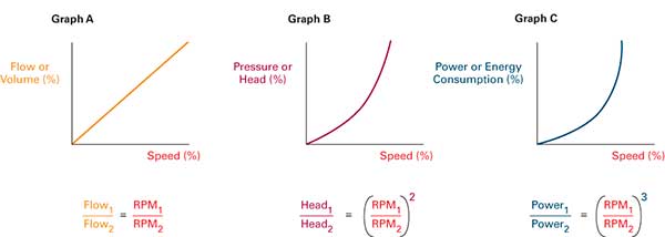 |
| Figure 1. The affinity laws 1. Flow/volume varies linearly with speed. (Graph A) 2. Pressure/head varies as a square of the speed. (Graph B) 3. Power or energy consumption varies as a cube of the speed. (Graph C) |
Determining the system curve (see Figure 2) is important to select the proper system pump. This curve describes what flow will occur given a specific pressure. Static head or lift and friction head need to be defined. Static head/lift is the height that the fluid must be lifted from the source to the outlet. Friction head is the power required to overcome losses caused by the flow of fluid in the piping, valves, bends and other devices in the system. These losses are flow-dependent and are nonlinear.
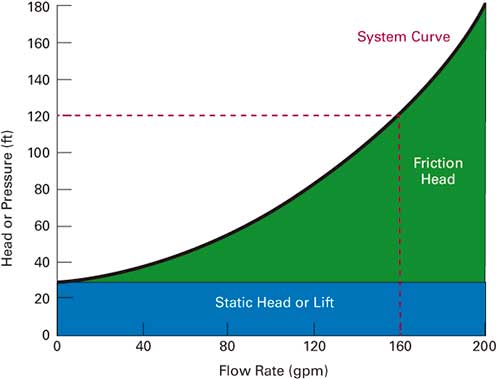 |
| Figure 2. Elements of a system curve |
In Figure 2, the system curve and pump performance curve intersect at the desired operating point of 120 feet of pressure and 160 gallons per minute of flow. The system will have a single operating point unless a device is added, and a pumping application rarely requires the pump to produce maximum flow.
VFDs Versus Throttling Devices
A mechanical throttling device is often used to limit flow. This is an effective control method. However, it wastes both mechanical and electrical energy. Energy use with a throttling device is shown in Figure 5. The lower curve shows energy use with a VFD. Since VFDs adjust the frequency of an AC motor, flow and energy consumption are reduced. The green shaded area shows the energy saved.
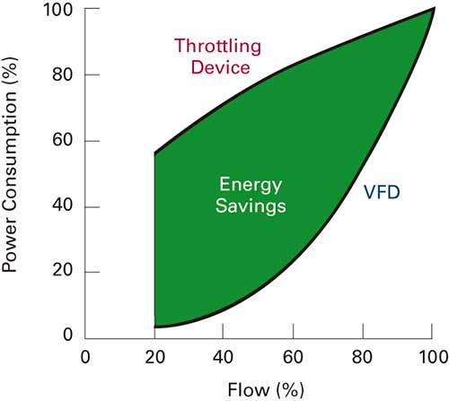 |
| Figure 5. The amount of energy saved by using a variable frequency drive versus a valve to control flow |
A throttling device is typically used as a mechanical way to reduce the flow rate in a pumping system. Applying a throttling device to the system changes the system curve (see Figure 3). The throttling device reduces the flow of the system, yet the pump curve is not changed. This wastes energy and creates mechanical stress. Since the pump operates at full speed, a tremendous amount of energy is used. Also, mechanical stresses on the pump system can prematurely result in seal or bearing failures.
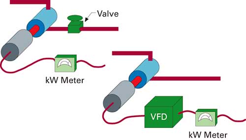 |
| Figure 3. A pumping system using a mechanical throttling valve and the same system using a VFD |
The addition of VFDs
VFDs electronically control power supplied to the motor, closely matching power requirements to produce a specified flow. This is similar to using a new pump with a smaller impeller.
To see the energy savings with VFD technology, Figure 7 combines Figure 4 and Figure 6. The blue shaded area demonstrates the resulting energy savings realized by using a VFD instead of a throttling device.
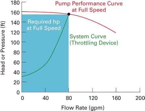 |
| Figure 4. System characteristics using a mechanical throttling device. The energy consumed is represented by the blue shaded area. |
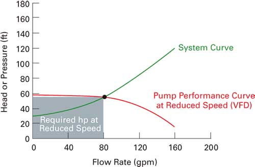 |
| Figure 6. The pump curve and the energy used with VFD control; note that the pressure is also reduced, helping reduce the mechanical stresses that are created with throttling devices. |
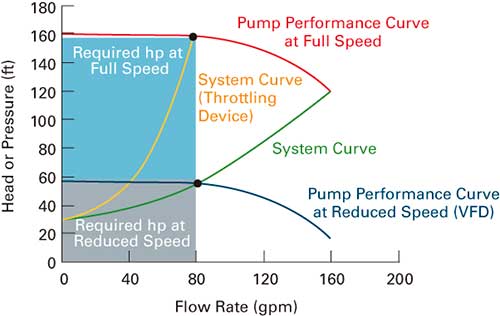 |
| Figure 7. The resulting energy saved by replacing a throttling device with a VFD |
By using VFDs, additional cost savings can be realized because fewer components are needed for valve control. With a throttling control system, losses occur in the valve, and additional piping is needed to bring the valve to a height at which it can be adjusted.
Because of these losses and the internal pump loss, to obtain a head equivalent to 50 horsepower, an equivalent of a 90 horsepower pump and a 100 horsepower motor is required. With a VFD, no valve or pipe losses occur because of bends or additional piping, reducing the piping losses to 8 horsepower. With the reduction of these losses, a smaller pump can be used with lower losses. For the same equivalent of 50 horsepower of head, only a 68 horsepower pump and a 75 horsepower motor are required. This results in a substantial system cost and installation savings, economically justifying the VFD.
Energy Savings & Extended Equipment Life
By matching power consumption to changing system requirements, VFDs are relied upon to provide steady, efficient power for variable speed pump applications. VFDs protect motor and pump assets by controlling power and minimizing the mechanical stress caused by starting and stopping the pumps.
The latest generation of VFDs is more efficient, accurate and refined—leading to increased energy savings. New and sophisticated technologies are impacting efficiency. Specifically, advancements in capacitors and DC link reactors, insulated-gate bipolar transistors, heat management, processing power and measuring technology enable the development of solutions to problems that were not recognized earlier. Additionally, new and advanced algorithms affect energy efficiency. P&S
