
One of the most common repairs on centrifugal pumps is replacing worn or damaged wear rings. To restore efficient, reliable operation and prevent catastrophic pump failure, it is critical to restore proper clearances between the stationary casing wear ring and the rotating impeller wear ring. Although many pump manufacturers provide clearances and dimensions, some do not. There are plenty of aging pumps around from now-defunct manufacturers for which dimension data is simply not available.
In such cases, the rule of thumb that follows provides some guidance for acceptable running clearances, or the minimum running clearance chart in American Petroleum Institute (API) Standard 610 can be used as a guide.
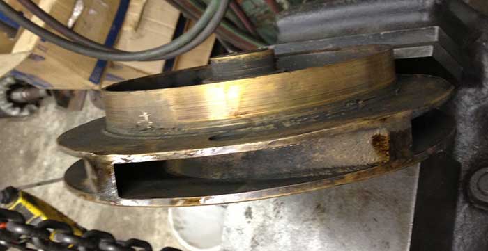 Image 1. Rear wear ring and balancing holes to limit axial thrust (Images courtesy of EASA)
Suction Side Wear Rings vs. Rear Wear Rings
Before proceeding, it is worth mentioning that there are basically two types of wear rings—suction side wear rings and rear wear rings—each of which serves its own purpose.
Suction side wear rings are designed to limit the flow of pumpage from the higher pressure discharge side of the impeller to the lower pressure suction side. Excessive clearance of these rings can result in increased flow across the suction side and a volumetric loss of efficiency.
Rear wear rings, when present, work in tandem with balancing holes that pass through the suction eye to lower the suction pressure behind the impeller and inside the rear wear rings (see Image 1), limiting the axial thrust force. Excessive clearances of rear wear rings can result in high axial thrust forces that can damage the thrust bearing.
Open vs. Closed Impellers
Pumps with closed-style impellers will include a casing wear ring and possibly an impeller wear ring that is fitted to the outside diameter (OD) of the impeller suction eye, both of which are suction side wear rings. These impellers may also have rear wear rings that control axial thrust.
Pumps with open-style impellers generally do not have suction eye wear rings, but they often have rear wear rings.
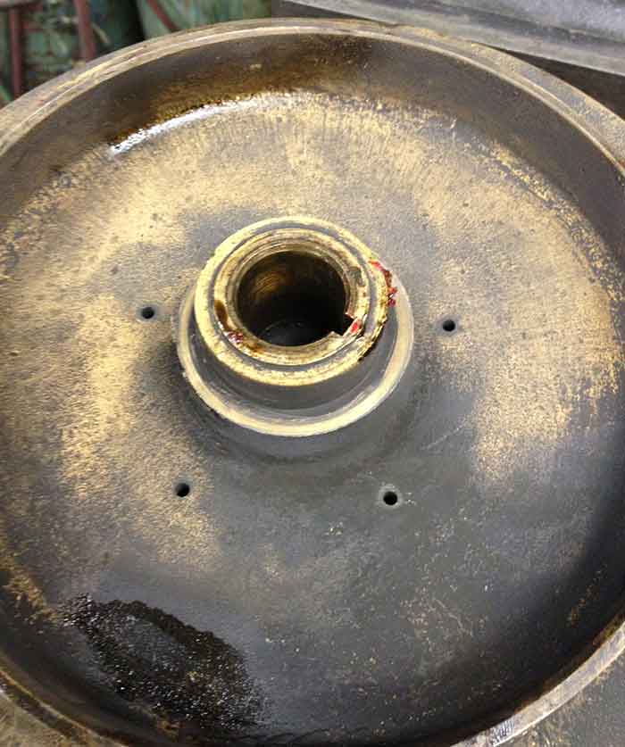 Image 2. Rear wear ring and balancing holes to limit axial thrust
Wear Ring Clearances & Specific Speeds
Wear ring clearances are more critical for certain types of impellers than others. The difference involves the relationship between the head and flow characteristics of the pump, which are described by the “specific speed” of its design. Note that the specific speed is not the pump’s rotating speed but simply a ratio of flow to head.
The higher specific speed impellers (to the right in Image 3) produce high flow but low head. Low specific speed impellers (to the left in Image 3) produce greater head at lower relative flow rate.
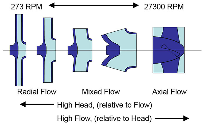 Image 3. Specific speed is related to head/flow.
Wear ring clearances are more critical for low specific speed impellers than for those with high specific speeds. Because these impellers have greater pressure differentials, any leakage across the wear rings will represent a greater percentage of the total flow than it would for high specific speed impellers.
Wear Ring Clearance Guide
Manufacturer’s tolerances are always the best guidance for evaluating as-found wear ring clearances and fitting replacement wear rings. When these are not available, the following guidelines work well for common water service pumps (municipal water, wastewater, HVAC applications, etc.) and apply to both suction side and rear wear ring clearance.
Another alternative is to consult the minimum internal running clearances chart in the API Standard 610 (API STD 610/ISO 13709). As illustrated by the example in Image 4, the values in the API 610 chart are very close to the general guidelines provided for new wear rings provided.
The API 610 chart provides values for wear ring diameters from 2 inches to 26 in. (50 millimeters (mm) to 650 mm) in 28 increments.
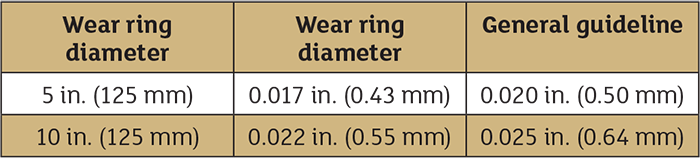 Image 4. API 610 minimum internal running clearances chart value comparison
The API 610 chart provides minimum, not maximum, clearances for pumps used in petroleum processing applications. Minimum clearances are specified since tighter clearances would risk contact between the rotating and stationary components, likely resulting in a catastrophic machine failure.
Therefore, when fitting new wear rings and manufacturer’s tolerances are not available, the API chart values provide a good guideline.
Note that wear ring clearances are always specified in diametric measurements—i.e., the difference between the inside diameter (ID) of the stationary ring and the OD of the rotating ring. That means the actual running clearance is one-half the diametric clearance.
The guidance provided above can be useful for designing replacement wear rings when manufacturer’s tolerances are not available. It can also be helpful for evaluating as-received clearances and deciding if replacement is necessary. Some manufacturers recommend replacing wear rings when clearances have increased by 40 percent of the original specified clearance. This recommendation is good for pumps in common water service applications and for impellers in the mixed-flow range of specific speed.
As described above, pumps with low specific speed impellers should be held to tighter clearances, whereas pumps with high specific speed impellers have more leeway.
Conclusion
Proper wear ring clearances are a fundamental concern for ensuring efficient and reliable pump operation. The guidance provided here should help pump users and service providers achieve those objectives.
General Guidelines for New Wear Rings
- General – up to 5 inches diameter 0.010 + 0.002 per inch of diameter
- General – 5 to 10 inches diameter 0.015 + 0.001 per inch diameter
- For galling materials, add 0.005 inch
