
This technique can accommodate different soil conditions and project schedules.
02/26/2015
Choosing the right dewatering method can be essential to ensuring a profitable beginning to any construction project. Before starting a project, contractors should consider the three most common methods for dewatering a site: open pumping, slurry walls and predraining.
Open Pumping
During open pumping, water is allowed to flow freely from the soil into the site as it is excavated. The water is then collected into sumps, ditches or French drains, where it is pumped out of the excavation and emptied into a suitable collection site. A French drain is a trench filled with gravel, rock or a suitable substitute and typically contains a perforated pipe that redirects groundwater to the sump area.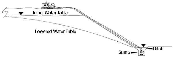 Figure 1. Hydraulically driven pumps used for sumping are recommended for suction lifts exceeding 30 feet. (Images and graphics courtesy of Thompson Pump)
Slurry Wall
A slurry wall is a water-blocking wall constructed of reinforced concrete that allows the foundation to be dug. This process is typically used for extremely deep excavations and for the construction of structures placed into bodies of existing waters. Pilings of steel sheets with tremie seals and pipes flushed with concrete can also be used to force groundwater to the surface.Predraining
The soil can be drained before excavation using wells, ejectors, vacuum wells, vertical sand drains, electro-osmosis or wellpoints. Most sites favor wellpoint dewatering. Although each site differs in terms of soil, hydrology and construction conditions, wellpoint dewatering is popular among contractors for its overall efficiency and adaptability.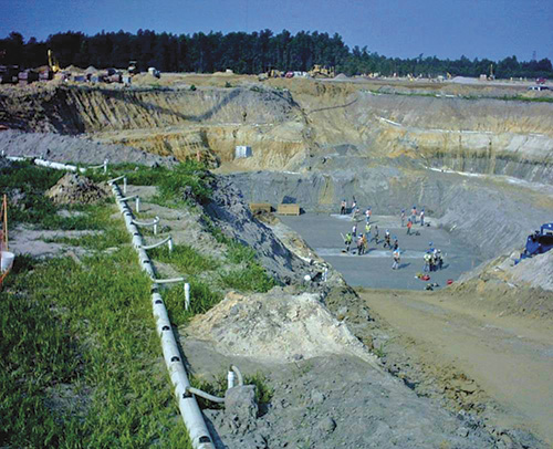 Image 1. Cofferdam dewatering using hydraulically driven pumps
Gathering Data
Before implementing a wellpoint dewatering solution, site managers must collect the following information:- The nature of the soil
- Groundwater hydrology (the movement, distribution and quality of water present)
- Size and depth of the planned excavation
- Proposed methods of excavation and ground support
- Proximity to and foundation details of any existing structures
- Design and function details of the structure to be built
- Planned construction schedule
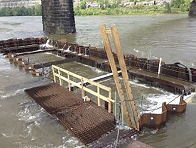 Image 2. Cofferdam dewatering was used to excavate and pour bridge foundations in a river.
Wellpoint Systems
Wellpoint systems dewater water-bearing soils, such as sand and gravel, so that excavation and construction of foundations can proceed with a dry and stable ground foundation. They keep the foundation dry during rain and flooding. In addition, wellpoints can stabilize soil, relieve pressure for dams and levees, and help supply water for municipalities and industrial plants. A wellpoint system encompasses a series of properly sized wellpoints that surround or run parallel to the site. Wellpoints are small-diameter tubes with slots near the bottom that are inserted into the ground. Before the excavation begins, these wellpoints are inserted into the soil and placed at the calculated spacing and depth by self-jetting into the ground. Some soil conditions require predrilling or hole-punching and sand casing before the wellpoints can be installed. This can be accomplished with a jet pump, which has a discharge that should be piped to an area where it will not interfere with the contraction. The wellpoint tubes are then connected to a header pipe with risers and swings piping. A dewatering pump is then connected to the header piping, creating a vacuum that pumps the water in the soils of the construction site to the discharge area.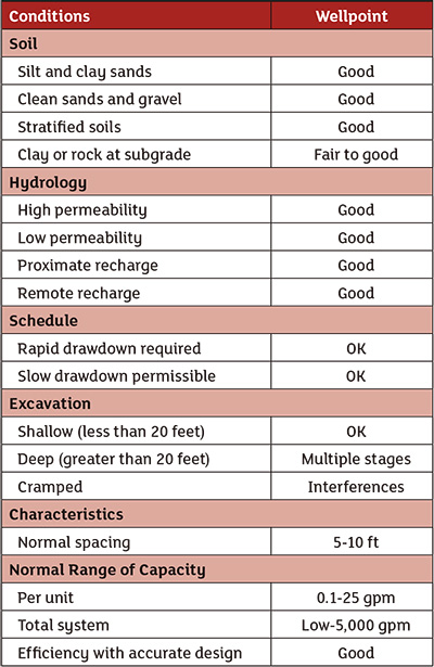 Table 1. The advantages of a wellpoint dewatering system based on soil condition, hydrology, project schedule and other factors
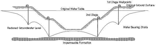 Figure 2. A diagram of a two-stage wellpoint dewatering system