

When put side by side, most cartridge mechanical seals look nearly identical. While some cartridge seals are designed for specific pumps or applications, such as American Petroleum Institute (API) services, most are what might be considered “generic,” designed primarily to fit the shaft size. This allows for seal standardization across a wide range of pump designs.
Designing cartridge seals to fit existing pumps is a challenge since most were originally built for packing, which requires much less space than a mechanical seal. The first seals to replace packing were component seals, made up of separate rotary and stationary parts. Installing them required handling delicate seal faces and assembling the parts on the pump shaft before pump assembly. Once set, the seal could not be moved, making impeller adjustments difficult during installation or operation.
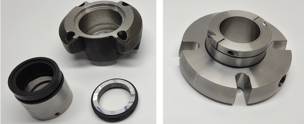
What Is a Cartridge Seal?
A cartridge seal combines all seal components into a single unit by adding a sleeve and collar, ensuring proper seal assembly into the pump without delicate handling or extra measurements.
The cartridge seal has many advantages affecting both installation and performance. For maintenance, installation is simpler and less prone to failure. The external shaft collar can be loosened after pump assembly, allowing for impeller adjustments. Modern cartridge seals include design features that improve performance and are assembled and tested in clean conditions to protect the faces from damage and contamination.
Installation Features
Gland gasket/bolt holes/slots
To accommodate variations in stuffing box dimensions and seal bolting across different pumps, cartridge seals typically use flat gaskets and slotted bolt holes. While the internal seal components are the same, oversized bore boxes require a cartridge seal designed for that bore style.
Setting/centering device
Since the seal is designed to fit the shaft, the gland and stationary seal components must be centered within the cartridge to prevent contact during operation. The centering device aligns the seal as well as setting the correct spring load.
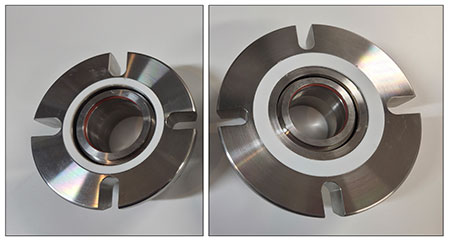
This device is typically a set of brass clips or an internal spacer. Clips must be removed after installation, while internal spacers remain in place during operation. The difference comes down to ease of installation—clips are more robust but add steps, whereas internal spacers simplify the process.
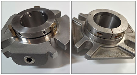
Shaft collar
The collar locks the seal securely to the shaft. This can be done with either a set screw or a clamp style collar.
Set screw collars, the most common type used on cartridge seals, have multiple set screws that bite into the shaft. Limited space can make tightening difficult, and the small screws can raise burrs or strip, causing removal issues or shaft damage.
A friction drive collar makes seal installation and removal easier while improving seal alignment, though it may slightly reduce pressure limits compared to set screws.
Performance Features
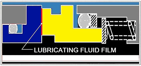
Seal faces
Seal faces are the heart of the seal. A rotating face and stationary face are seated against each other by spring force and hydraulic pressure to prevent leakage between them. Made from carbon graphite, silicon carbide or tungsten carbide, they are engineered to stay flat so a thin film of fluid can lubricate and cool them. Maintaining that flatness is the key to long seal life.
One face is spring-mounted to compensate for misalignment, shaft movement, vibration and bearing play.
Much of a mechanical seal’s technology lies in the design of its faces. With limited space, fitting the seal face into a cartridge while achieving proper hydraulic balance and maintaining flatness is a challenge. Finite element analysis (FEA) helps evaluate how pressure and temperature affect face distortion based on geometry and material properties, revealing clear differences between two face types—composite and monolithic, with each reacting differently under the same conditions.
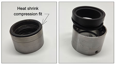
A composite face combines two materials—the sealing face and a metal holder. A monolithic face, by contrast, is made entirely from a single material.
The composite design uses heat to shrink-fit the face into a metal holder, saving space and reducing cost. It performs well in low-temperature, low-pressure and low-speed applications but can lose flatness under harsher conditions, causing leakage or seal failure.
The design of monolithic faces is straightforward since they are made from a single material. FEA ensures that they stay flatter and more stable across a wide range of operating conditions.
Seal face drive
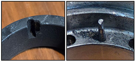
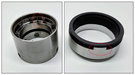
Another key feature is the drive mechanism. When the pump starts, each seal face must either rotate or remain stationary as intended. This is usually achieved with small drive pins.
Contact between the face and drive pin, combined with movement or vibration, causes wear on the spring-mounted face. This wear can lead to hang-up, resulting in leakage or seal failure.
A heavier-duty drive, such as a lug drive, helps reduce wear—especially in frequent start/stop or high-vibration applications.
Springs
Spring force keeps the seal faces closed during startup and when hydraulic pressure is low. It also provides flexibility to handle misalignment and vibration. Springs may be configured as a single spring or as multiple springs. Multispring designs are often preferred because they provide more uniform face loading.
Seal face misalignment tends to be greater on the stationary face than on the rotary face. Because the rotary face mounts directly to the shaft, it allows for better alignment control, while the stationary face is mounted through multiple components—including the gland, gasket, stuffing box and pump frame—increasing the potential for misalignment.
Springs can be placed behind either the rotary or stationary face. A stationary spring design minimizes shaft runout and vibration effects, improving face alignment and extending seal life. It also keeps the springs out of the process fluid, protecting them from clogging and corrosion.
Flush and quench
Pipe taps in the gland—referred to as environmental controls—are the final seal feature to consider. A seal may be designed with both flush and quench ports.
The flush port is on the process side of the seal and can be used in two ways. The first use is to circulate process fluid around the seal to cool or heat it, or to increase or reduce pressure for improved lubrication of the seal interface. The second is to flush the seal with an external fluid, providing improved lubrication and cooling.
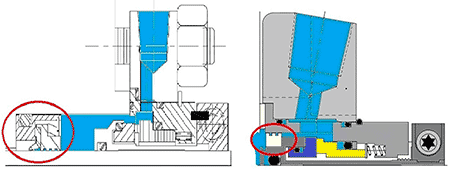
When using a flush, it is best practice to include a throat or containment bushing to control flow. The bushing maintains close clearance to manage pressure and minimizes the use of external fluids like clean water. A seal manufacturer can help determine the proper flow for an application. The bushing is typically installed directly in the stuffing box, though some seals incorporate the bushing within the seal itself.
A quench, with inlet and outlet ports on the seal’s atmospheric side, helps prevent leakage buildup that could cause face hang-up and can also be used to monitor leakage. Typically, quenches are rarely used in general industry but are common in crystallizing or coking applications.
