
Changing motor performance can impact interconnecting equipment.
Engineered Software, Inc.
06/12/2018
Editor’s Note: Jeff Sines is a member of Ray Hardee’s team at Engineered Software, Inc.
A fluid handling system involves various interconnected equipment designed to use the mass and energy of a flowing fluid to perform work, transfer heat or facilitate processes to make a product.
The configuration of the system, the fluids used and the purpose of the system will vary depending on the application. Because of the complexity of most systems, it can be difficult to understand how systems operate and how to troubleshoot and optimize them.
To understand a complex system, one of the key questions to ask is, “What drives the process?” The design requirements drive the decision on what equipment is needed and what process conditions (flow rates, temperatures, pressures, tank levels, etc.) to establish. The fluid properties and the equipment performance drive the amount of hydraulic power the pump must add to the fluid to satisfy the system requirements. The pump performance then establishes the amount of mechanical power needed from the motor. In turn, the motor performance drives the amount of electrical power needed to achieve the ultimate goal of the fluid-handling system.
In this chain, there are fundamental engineering principles, concepts and mathematics that help us understand how the equipment interacts with each other. As an example, see how the affinity laws can be used to understand how the centrifugal pump performance is driven by its motor performance.
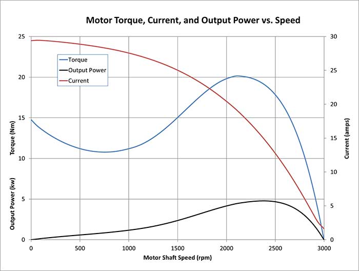 Image 1. Motor A performance curves (Images courtesy of the author)
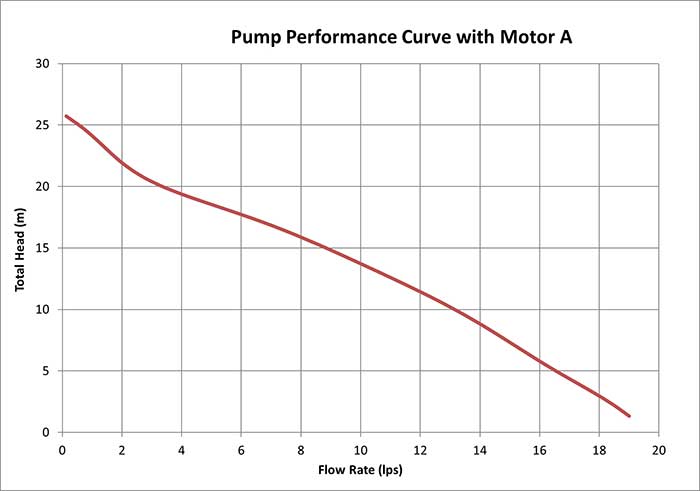 Image 2. Pump performance using Motor A
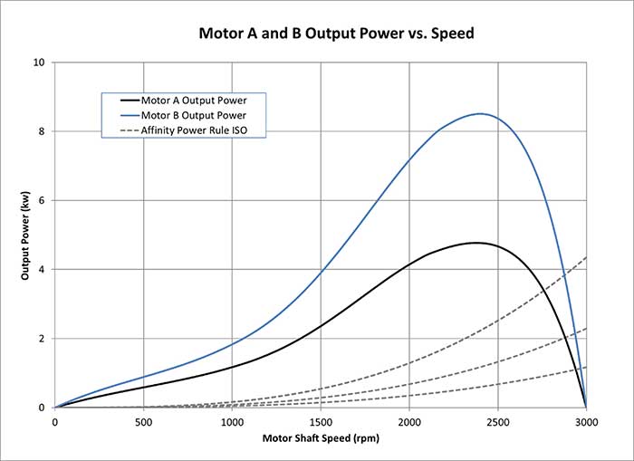 Image 3. Motor A and B performance curves with ISO lines of constant proportionality for the affinity power rule
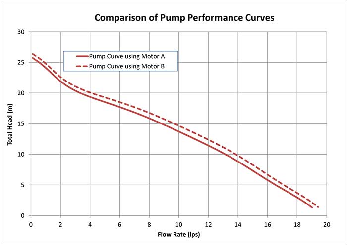 Image 4. Shift in pump performance with a larger motor
The Driver of the System
A fluid handling system consists of various equipment with hydraulic performances defined by various methods, including the use of the flow coefficient for control valves, the discharge coefficient for flow meters and the resistance coefficient of pipes, valves and fittings. The hydraulic performance can also be defined by a performance graph developed by the manufacturer by operating the equipment in a test system most commonly seen with centrifugal pump performance curves. Electrical equipment also has defined performance characteristics, seen with the motor performance graphs. Changing the performance of one component can impact the operation of interconnecting equipment and the overall system, as shown by using the affinity rules to evaluate the effect of changing the motor on a pump. Since the motor performance defines the amount of shaft power developed as a function of shaft speed, the pump’s power curve is the motor’s power curve. Changing the motor changes the power curve, which in turn changes how the pump distributes this power in the form of total head and flow rate, showing that the motor is truly the driver of the system.
To read more Pump System Improvement columns, click here.
