
Editor’s Note: Jeff Sines is a member of Ray Hardee’s team at Engineered Software, Inc.
How do you get equal flow to components in your piping system with minimal interruption and fine tuning of control valves? In systems with multiple branches and loops, the flow will take the path of least resistance. In an uncontrolled system, there will be an inherent difference in flows to components with a common source.
This is affected by many factors, including pipe size, length, roughness, material, fittings, bends and much more. I have even seen operators add extra bends and fittings on one branch to match the geometry of another to maintain equal flow through each branch. While this should work, it comes with a host of drawbacks like additional cost for components, decreased overall system efficiency and issues when components fail and repairs must be made.
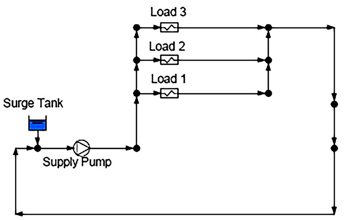 Image 1. Reverse return closed loop system. (Images courtesy of the author)
One option that can potentially help is the reverse return system. While many engineers have not heard of this simple trick, it has been used extensively for years in the heating, ventilation and air conditioning (HVAC) industry to help balance flows. HVAC has many identical devices that require equal amounts of flow, such as boilers and chillers along with their respective heat emitters. This could apply to any number of processes, from the advanced where machinery needs reliability and repeatability to the simple filling of multiple tanks at a similar rate.
The easy way to remember the basics of a reverse return system is with the acronym LIFO (Last In, First Out).
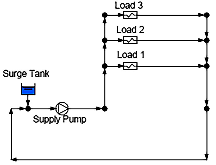 Image 2. Direct return closed loop system
A reverse return system is a type of closed loop system where the return header is connected to the most hydraulically remote load, as shown in Image 1. Compared to the direct return system in Image 2 where the return header is connected to the load closest to the pump, the reverse return system distributes the flows and pressures more evenly across the system, making it inherently balanced.
The inherent balance of the reverse return system can be shown when modeled in computer software and the systems are calculated. Let us first look at the pressure and flow distributions in the direct return system. Image 3 shows the direct return system with no controls on the loads and the pump sized for 450 gallons per minute (gpm), designed for 150 gpm through each identical load.
Image 3. Direct return system calculated. Pump sized for 450 gpmThe inlet pressure to each load decreases the farther the load is from the pump discharge, and the outlet pressure of each load decreases the closer the load is to the pump suction. This creates a larger differential pressure at Load 1 and a decreasing differential pressure across each load the farther the branch is from the supply pump. This differential pressure profile causes the flow rate to decrease from 155.9 gpm at Load 1 to 145.9 gpm at Load 3, a 10 gpm (or 6.4 percent) variation from minimum to maximum flow rate. The pressures and flow rates are summarized in Table 1.
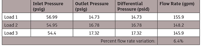 Table 1. Pressure and flow distribution of direct return system
Image 4 shows the calculations for an identical system with the exception of an additional length of piping on the return header to create a reverse return system.
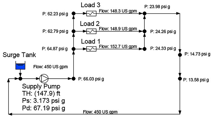 Image 4. Calculated reverse return system. Pump sized for 450 gpm
Just as with the direct return system, the inlet pressures to each load decrease the farther the load is from the pump. However, with the return header connected to Load 3, the outlet pressures decrease from Load 1 to Load 3 (opposite of the direct return system). This causes a smaller variation in the differential pressures across each load in the system. The inherent balance of this reverse return system produces a flow rate variation of 4.4 gpm, or just 2.9 percent. Table 2 summarizes the pressure and flow distribution in the reverse return system.
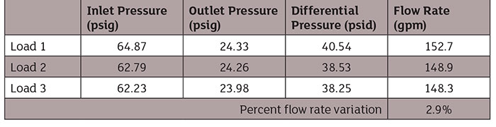 Table 2. Pressure and flow distribution of the reverse return system
There are a couple of additional points to note about the calculated results for the two systems. Because the reverse return system requires an additional length of pipe at least the length of the return header, there is additional head loss that must be overcome by the head of the pump. This requires the total head of the pump in the reverse return system to be higher than the direct return system (147.9 feet vs. 129.7 feet in this example). Along with the added capital cost of the extra piping, the increased pump head results in higher operating cost and may require a larger pump and motor to meet the demands of the system.
Also, the increased pump head results in higher discharge pressures, which may affect the selection of pipe material or schedule and the capital costs of the piping.
The benefits of an inherently balanced system may outweigh the additional costs that may be incurred. Depending on the need for exact control of flow for each load, it may be possible to design the system without costly flow control valves and eliminate the associated controllers, wiring, pneumatic tubing and other support instrumentation. Conduct an in-depth cost analysis to determine the best solution for any given application.
To read more Pump System Improvement columns, click here.
