

In the August 2020 issue, I started this discussion about why some impellers have holes in them, or why some impellers have funny mini-vanes on the back side. The short answer, as I stated last month, is to reduce axial thrust, reduce the pressure in the stuffing box (seal chamber) and to preclude the collection of foreign debris in the annulus (chamber) behind the impeller.
Here is where we left off from Part 1 of that column (which you can find at www.pumpsandsystems.com/author/jim-elsey).
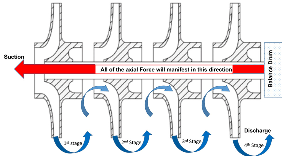 IMAGE 1: Typical multistage pump with impellers all facing in the same direction (Images courtesy of the author)
Balance Drums
In larger and higher horsepower multistage horizontal pumps, all of the impellers face in the same direction (toward suction) and the resultant axial force is almost negated by the use of a balance drum (or simply “drum”). The drum may be of either a straight or stepped design (aka, “two diameter drum”). Some pumps will use balance rings and/or balance discs; these will not be covered. Of interest, know that the axial force can exceed several tons in these pumps.
The drum is keyed and fixed to the shaft after the last stage and, therefore, it rotates at the same speed as and at a fixed position on the shaft. The drum rotates inside of a close clearance stationary throttle bushing. This rotor arrangement and drum geometry permits a small and fixed amount of product leakage back to a chamber that is at or near suction pressure. On a two-diameter drum, the variable axial position of the shaft allows either more or less leakage at any instant to change the chamber pressure on the low pressure side and counteract the axial force. This action occurs instantaneously and automatically as a direct function of the simple design. The amount of total axial movement of the rotor in this evolution is very small—perhaps a few thousandths of an inch.
It is not the intent of this column to describe the balance drum operation in more detail, but a basic description would explain that by using discharge pressure on one side of the drum and suction pressure on the opposite side, the majority of the axial forces will be balanced. Not all balance drum designs will balance the full magnitude of axial thrust as the pump operates over the entire range of its curve, so it may become a case of “caveat emptor,” or in English, “let the buyer beware.”
When you choose a balance drum in the pump design, there is the added cost and complexity of the component itself and its subsequent incorporation into the pump along with the added maintenance. Setting the balance drum clearance(s) in the field is a tedious and complex task that is frequently done incorrectly, all of which leads to expensive damage and downtime. Balance drum designs may also experience significant difficulty with system pressure transients, so always design (size) to have some residual thrust (versus total negation at ideal conditions) with the calculated leakage rates adjusted for a high wear condition. The drum leakage rate does reduce the pump’s efficiency, but in my opinion, it remains an acceptable tradeoff compared with alternative designs in this power range of pumps.
Opposed or Back-to-Back Impellers
A common example of a back-to-back arrangement would be a pump where two single-stage closed impellers are placed back-to-back, one facing each direction so as to balance the axial forces. A partition and/or pressure breakdown bushing between the stages keeps the stage pressures separated. This design balances the thrust almost perfectly and there is little to no reduction in efficiency.
In other large, multistage pump designs, the axial force is managed by using an opposed impellers method, just on a different scale from the back-to-back illustration. For example, in an 8-stage pump, four impellers face one direction and the other four face the opposite way. In this manner, most of the axial force can be reduced. Note that the number of stages facing in one direction is not always an even number when compared to the number facing the opposite direction. On pumps of this style, and especially with four or more stages, you must be vigilant to ensure the rotor is correctly positioned (axially) or there will be issues (damage) with the thrust bearings regardless of type.
The potential remains for high pressure differentials (pressure breakdown) between stages in these pumps and as the wear and subsequent leakage increases with time the thrust will also increase. Years ago, A.J. Stepanoff conducted lab tests on a two-stage (back-to-back) pump. He measured an increase in axial thrust from an initial 200 pounds with the interstage bushing clearance at 0.014 inches to over 1,050 pounds when the clearance increased to 0.060 inches. On many multistage pump models, the downside of the opposing impeller concept is if your system requires an odd number of stages to meet a specific hydraulic condition point. Opposing impeller pumps require a “crossover piece” somewhere in the pump to redirect the flow direction. The crossover casting increases the cost and complexity of the pump.
One last comment on multistage opposing pumps. For this design, there are X number of impellers facing different ways, consequently there are both right-handed and left-handed impellers, and often the first stage is totally different from all the rest (different inlet eye to address net positive suction head [NPSH] issues). To most people and untrained mechanics, all of the impellers will look the same. What could possibly go wrong?
The issue of addressing and designing for the pressure breakdown between stages becomes, in my opinion, a game of “whack a mole.” The hypothetical question is: Do you design to contain the pressure per stage, or for some portion of the pump, or for all the stages? For example, on a two-stage pump set up with back-to-back impellers, there is a bushing requirement to contain/control the pressure between the two stages and again at the high side stuffing box. To carry that idea forward, on an 8-stage pump, do you design to break down the pressure after each stage, after four or after all eight?
Dual Suction Impeller
A common example and a slight variation to opposed impeller designs is used on single-stage horizontal split case pumps where one impeller has two symmetrical inlet “eyes” in opposition at 180 degrees to each other. These dual suction impellers are also referred to as double entry impellers. In principle, the net effect is a fully balanced axial force. In fact, the dual suction design is the most successful (but not necessarily the most cost effective) of all the methods. The thrust bearing for these pumps is only required for upset conditions such as startup and shutdown and other off-design operations.
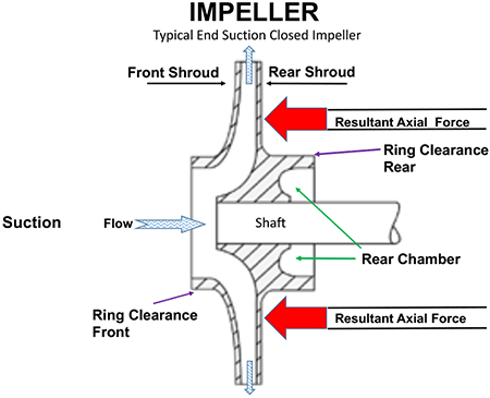 IMAGE 2: Single-stage end suction closed impeller. The resultant axial force will be in a direction toward suction.
As is the case with all pumps, the opposing forces are never fully balanced due to minor differences in the casings and impellers. Understand that these parts are typically cast and carry the potential for imperfections and/or asymmetry inherent to castings. The dual suction design is also limited in the number of stages that can be practically applied, usually three at maximum. At more than three stages, the pump simply becomes too long.
Dual suction impellers may also be applied on the first stage of high end vertical pumps and are frequently used for condensate applications because the net positive suction head available (NPSHa) for these systems is so low and the dual eye impeller requirements for net positive suction head required (NPSHr) will typically be 50 percent of a standard impeller.
Closed Impellers & Use of Back Rings
Closed impellers have both front and back shrouds, and so the surrounding pressure works from both sides of the impeller. There will be a resultant mismatch in the axial force due to the asymmetry of the impeller eye area. The result is less force acting on the eye area and results in a higher force acting on the rear shroud pushing the impeller toward suction.
To counter the thrust mismatch, many single-stage end suction pumps with closed impellers will incorporate a back ring on the rear shroud to reduce the axial thrust. (Some technical references refer to this back ring as an annular seal.) Adding the back ring to the impeller and drilling balance passages (holes) in the impeller shroud creates an area of lower pressure in the chamber behind the impeller. The lower pressure yields a lower axial force. An alternate and, in my opinion, a better design choice is to create an internal passage in the casing back to suction in lieu of drilling balance passages (holes) in the impeller shroud.
The back ring (annular seal) has a similar geometry and appearance of a front wear ring, however, the main purpose is different. The rear ring is there to simply reduce (pressure breakdown) the product leakage into the chamber. Again, by creating the low pressure chamber on the back side of the impeller, the force is reduced.
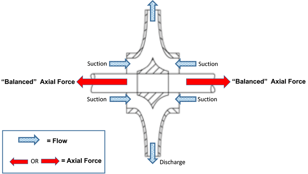 IMAGE 3: Dual suction Impeller. Axial force is balanced.
This back ring feature is common on pumps in heavy industrial and other critical services including many American Petroleum Institute (API) 610 applications. One advantage of the design is that thrust mitigation is not a direct function of the rotor’s axial position. A caveat with this design is that as the back ring clearance wears the effect is diminished. As a result, the magnitude of axial thrust will vary with the ring wear. Some designs will handle this issue better than others due to a better understanding of all of the principles involved, consequently a more accurate calculation of the total area for the balance passages as compared to the annular clearance. Proper sizing and placement of the annular ring as a ratio and proportion of the balance bleed passages is both paramount and critical.
Note that some closed impeller designs will use pump out vanes on the rear shroud, a feature that will be covered in more detail in another section. Some closed impellers will also incorporate pump out vanes on the front shroud of the impeller for the sole purpose of keeping debris away and do not exist for axial thrust mitigation. Other closed impeller designs use pump out vanes on the rear shroud more to rid the area of debris than to reduce thrust.
Not often used in industrial pumps, but some commercial pump casings will incorporate stationary (static) vanes or fins as an integral part of the casing at the front of the impeller to reduce axial thrust.
Part 3 of this column will appear in the next issue of Pumps & Systems.
References
1. K.J. Zanker—Experiments with back vanes used for balancing axial thrust, British Hydromechanics Research Association, 1962
1. Lev Nelik—Pumps & Systems article, November 2013, www.pumpsandsystems.com/reducing-thrust-and-extending-bearing-life
3. Marek Szlaga—Balancing Axial Force, Institute Engineering, Warsaw, Poland, 2019
4. JF Gülich—Centrifugal Pumps, 2014
5. A.J. Stepanoff—Centrifugal and Axial Flow Pumps, 1957
6. Sam Yedidiah—Centrifugal Pump Users Guidebook, 1996
