

An aftermarket service provider used its services and technologies to provide an analysis, repair and testing solution for a power plant’s failing vertical pump.
A combined-cycle power plant uses two vertical pumps for condensate extraction. The two pumps were on a scheduled repair cycle, which was drawing near. Each condensate pump is rated for 100% unit load, enabling the plant to run one pump or the other. One of the pumps—installed for less than three years—was already showing severe signs of degradation, while the other pump was operating acceptably. The plant engaged the full services of an aftermarket service provider, which was able to resolve the root cause and improve the pump’s overall performance.
Challenge & Solution
While one of the pumps was operating acceptably, the second pump had high vibration levels due to structural resonance coinciding with a subsynchronous forcing function (bearing whirl). Additionally, the end user found a 10% deficiency in total developed head for this pump compared to the OEM performance curve. This pump had been removed from service and repaired three years prior due to similar behavior. However, the root cause of the problem was not addressed at that time.
The aftermarket service provider delivered a comprehensive solution by coordinating with its multiple divisions to provide a health audit (field performance testing) and field troubleshooting, modal analysis, finite element analysis and structural design modifications. The service provider also performed equipment repair, laboratory performance testing, field commissioning, performance validation and provided wireless condition monitoring for the user.
Work Scope
1. Health audit
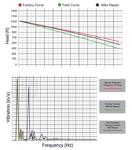
The service provider performed field performance testing to evaluate the two installed condensate pumps’ overall mechanical and hydraulic health. The investigation uncovered two concerning conditions on one of the installations during the on-site review of the collected data. One pump was found to be nearly 10% lower on total developed head compared to the OEM performance curve and had much higher vibration than the sister pump (>0.6 inches per second [in/sec] peak).
2. Troubleshooting
Based on the collected vibration data, the aftermarket service provider’s field engineers suspected that the pump was suffering from resonant excitation, which occurs when an operational frequency or forcing function closely approaches the natural frequency of a component (resonance always requires a forcing function to excite). In this case, the service provider determined that the forcing function was bearing whirl, characterized by vibration energy in the range of 0.4x to 0.48x revolutions per minute (rpm). Bearing whirl is an operating condition wherein fluid inside the pump bearings can begin to “push” the pump rotor at a frequency slower than that of operating speed (subsynchronous vibration).
3. Modal analysis
The preliminary results were discussed with the user and the service provider recommended a modal analysis, which is a structural natural frequency study that involves instrumenting the structure with numerous tri-axial accelerometers and impacting it with a calibrated modal hammer that is equipped with a force transducer. This testing aims to identify the structural natural frequencies present and the associated mode shape of each resonance. The collected vibration data is then imported into a software that can animate each identified natural frequency’s resonant mode shape—understanding the mode shapes and their damping characteristics helps to better understand how to modify the structure to shift the offending resonance out of excitation. The modal analysis data confirmed that a structural resonance was within 3.8% of the bearing whirl forcing function.
4. Finite element analysis (FEA)
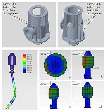
It was essential to both the end user and the aftermarket service provider to resolve this problem economically and on the first try, so the service provider decided to use FEA to determine the final corrective action. FEA is a mathematical model of the installation that allows engineers to simulate the equipment’s behavior under given conditions. As part of the FEA, several (computational) structural modifications were made to the pump discharge head, allowing the field engineers to predict the associated shift of natural frequency with each structural modification. A benefit of this type of engineering analysis is that it eliminates trial and error in the field, quickly becoming costly for the end user.
5. Structural modifications
As a result of the finite element analysis, it was determined to add additional stiffening ribs to the pump discharge head to increase the margin of separation between the frequency of the forcing function and the natural frequency. To prevent resonant excitation, it is ideal to have a +/- 15% separation margin of these frequencies. Based on the FEA modifications, the service provider predicted that the unit would obtain nearly a 20% margin of separation (previously, a 3.8% margin of separation of the frequencies existed).
6. Equipment repair
The end user brought the pump to the aftermarket service provider where it was disassembled and inspected. One of the inspection’s key findings was that the wear rings of the impellers were not fully engaged within the case rings of the bowls. The rotor had been lifted too high. This explained why the hydraulic performance was so low and a portion of the increased bearing whirl forcing function.
7. Laboratory performance testing
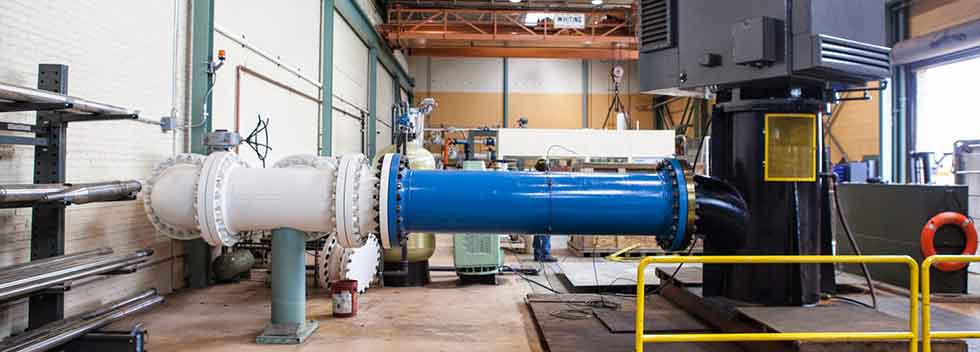
To prove that the bearing whirl forcing function had been adequately reduced and to validate that the hydraulic performance deficiencies were resolved, the service provider tested the pump at its performance test lab. The performance test results showed that the subsynchronous bearing whirl vibration was reduced to acceptable amplitude levels. Hydraulically, the service provider found the pump to perform acceptably according to the Hydraulic Institute standards.
8. Field commissioning
The modified and repaired pump was installed under the supervision of the field service team.
9. Field performance validation
Once the service provider completed the installation, the field service team performed additional impact testing on the pump and motor. The specialists determined that a separation margin of 21% existed between the previously identified forcing function and the structural natural frequency. Overall vibration amplitudes at the top of the motor were found to have reduced from ~0.6 in/sec peak to 0.07 in/sec peak. Hydraulically, the service provider found the pump to be performing within 1% of the performance curve provided by the test lab.
10. Wireless condition monitoring
Wireless vibration sensors were installed to enable remote monitoring of vibration and surface temperature. The aftermarket service provider used various software packages, enabling more in-depth insight into the vibration and modal analysis data. Additionally, computer-aided design (CAD) and FEA applications were used to model the installation and to perform the finite element analysis.
Results
This pump had lasted only three years between repairs, which is markedly below its expected life cycle. With the extensive modifications, the pump is now expected to run for 10 years. The pump rotor is now correctly positioned. The vibration amplitudes have reduced to 0.07 in/sec peak (actually lower than the sister pump), and hydraulically, the pump is operating as per the test lab’s performance curve.
This project involved nearly every division of the aftermarket service provider. Field engineering identified and diagnosed the equipment’s condition, then worked to develop a structural modification to shift the resonance outside the range of excitation. The service center repaired the pump and upgraded the line shaft bearing geometry to reduce the bearing whirl effect. The performance test lab tested the pump, and the field engineers went back to the field with the pump to commission the unit and ensure acceptable performance. Also, wireless vibration sensors were installed to enable operators to monitor vibration and surface temperature remotely.
Case Study: On-Site Troubleshooting & Testing Diagnoses Resonance in Vertical Condensate Pumps from Hydro, Inc. on Vimeo.
