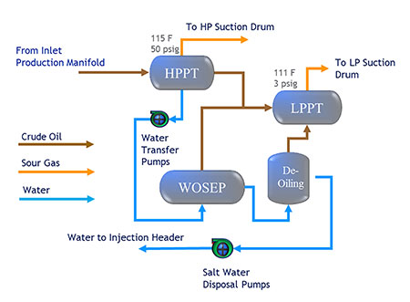
Produced water transfer pumps, G-204, transfer the produced water separated in the high-pressure production trap vessel (HPPT) to the water oil separation vessel (WOSEP) as illustrated in Image 1.
When the pumps were first purchased, the pumps’ data sheet indicated that the pumps’ media properties shall contain no total suspended solids (TSS). After operation and pumps’ short meantime between failures (MTBF), it was discovered that the media properties of the produced water contained over 100 milligrams/liter (mg/L) of TSS.
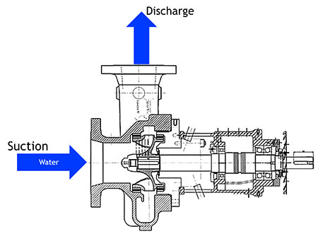
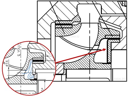
The water transfer pump is an overhang pump design. The 200-horsepower (hp) pump is capable of producing a total rated head of 211 feet with capacity of 2,100 gallons per minute (gpm). Image 2 shows the pump cross-sectional drawing and specification.
Technical Discussion
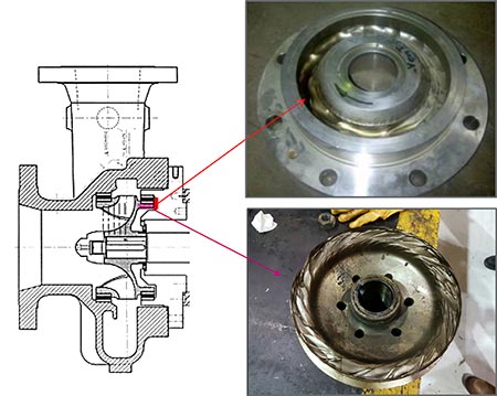
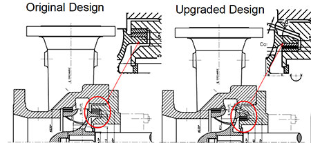
The root cause of the pumps’ short MTBF was sand particle accumulation and turbulence at the pumps’ rear shroud. Image 3 shows a pump’s rear shroud condition during its overhaul.
The sand particles are centrifugally forced to the top rear shroud and wear ring area where the sand particles accumulate. The cross-sectional drawing of the pump, Image 3, shows the location of the erosion and sand particle accumulation.
Design Modification
The pumps went through a design modification to overcome the unexpected media change. The design modification focused on three main aspects.
- The first was to smoothen the flow at the particle accumulation areas.
- The second was to lower the centrifugal force exerted on the particles.
- The third was to improve particulate flushing by the balance hole.
To achieve the three aspects mentioned, the design upgrade consisted of the following seven design changes.
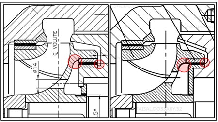
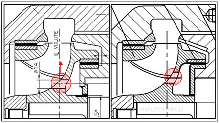
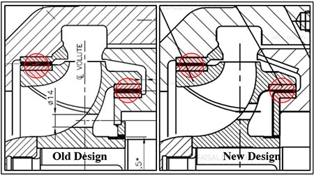
1. Lower the wear ring media passage
F = m.w2. r
Where:
F = force
m = mass
w = rotational speed
r = radius
Equation 1
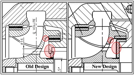
Pump wear rings were lowered with respect to the shaft (Image 4). Lowering the wear ring will lower the radius created, which is needed to lower the centrifugal force exerted on the sand particles.
2. Increase flow at the back of the impeller
Increasing the flow at the back of the impeller will allow flushing the sand particles accumulated from the back of the impeller.
Q = ρ.A.v
The increase of flow was achieved by the above equation: increasing the clearance (A) will decrease velocity (v), and, therefore, by the Bernoulli effect, the pressure of the media will increase, creating a drag force that will overcome the centrifugal force exerted on the particles.
3. Increase radius of curvatures at the back of the impellers
The radius of curvatures at the back of the impeller was increased to ensure a smooth, laminar flow and avoid any media turbulence excitation. Image 5 shows the radius of the curvatures once increased.
4. Balance holes modification
The design modification to the balance holes included increasing the balance holes size and raising its location upwards (Image 6). This modification allowed ease of accumulated particle flushing. This was done after confirming thrust calculations, which revealed improvement and reduction of 5 percent thrust force.
5. Wear ring clearance increase
The wear ring clearances were increased to direct more flow to flush the sand particles accumulated. The clearance increase also had an impact in reducing the achieved axial thrust force by 5 percent. Image 7 shows the location of increased wear ring clearances.
6. L-shaped case cover wear ring integrated with thrust bushing
Compared to the older design, the L-shaped case cover wear ring/thrust bushing design (Image 8) will lower the chances of turbulence excitation and particulate accumulation at sharp edge areas. The smooth, straight face had a great effect on smoothing the flow at that location.
7. HVOF coating application
To add an extra layer of erosion protection, a high velocity oxygen fuel (HVOF) coating was added to the erosion spots. Image 9 shows the HVOF-coated areas. Once one pump was upgraded with these design modifications, the pump was put back into operation and operated after about 24 months with no process or mechanical abnormalities detected. The pump internals were also inspected and no erosion spots were spotted and found in healthy condition. The design modifications were successful in making the pumps compatible with the new media properties.