

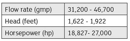
Seawater supply pumps (Image 2) ship seawater from the seawater distribution ring at the coast to the reservoir. These super pumps feed five seawater injection pumps. The pumps run in parallel operation with the below parameters found in Image 1.
The suction line distributes flow to two first-stage impellers, which discharge to two second-stage impellers of opposed design (Image 3).
History of Failure
In September 2012, both units experienced similar second-stage impeller vane leading edge breakage and impeller wear ring coming out. A study was carried out by the pump vendor and a third-party material laboratory. They determined the root cause was peak stresses in the second-stage leading edge of the vane, which reached the material strength of 316 stainless steel (SS). The impeller material was recommended to be upgraded to super duplex stainless steel (American Society of Testing and Materials [ASTM] A 890 Gr. 5A Type CE3 MN). In addition, the impeller shrink fit was found to be high (0.003 inch to 0.005 inch), contributing to high residual stresses at the base of the inlet vane location.
In December 2018, pump unit-A experienced suction pressure fluctuations and tripped on high radial vibrations. Pump unit-B experienced a high surge and tripped on low suction pressure. The surge lasted for 30 minutes and pressure variations ranged from 40 to 516 pounds per square inch gauge (psig). Pump unit-B was successfully restarted. Unit-A was shut down later after unit-B was successfully put back into service after being overhauled with a spare rotor in February 2019.
Immediate Recommendations
The following actions were agreed to extend the life of the second-stage impellers and eliminate the source of the inlet vane cracking:
- The impeller material was to be upgraded from austenitic stainless steel (ASTM A 351 gr. CF3M) to super duplex stainless steel (ASTM A 890 Gr. 5A CE3MN).
- The interference fit between the impeller and shaft was reduced from the range of 0.003 to 0.005 inches to 0.001 to 0.003 inches.
- The wear rings were eliminated, and the wear surface on the impeller was overlayed with tungsten carbide using a direct laser deposition (DLD) process.
Findings
During rotors inspection for unit-A and unit-B in the proponent pump shop, there were four identified failure modes, which were addressed separately:
- second-stage impeller structural failures
- impeller wear ring looseness
- first-stage impeller cavitation
- excessive impeller shrinks fit
Both failed pumps had second-stage impellers of original material 316 SS.
Second-Stage Impeller Failures in Unit-B
The Unit-B second-stage impeller left-hand side (thrust side) vane leading edges broke before the last trip on high radial vibrations. The vanes were damaged symmetrically. The fracture surface was smoothed by the flow. There were cracks, with damage extending further in the vane as a result of pressure pulsation, as shown in Images 4 and 5.
Second-Stage Impeller Failures in Unit-A
The unit-A second-stage impeller right-hand experienced the loss of a large piece of vane and a crack in another vane. The crack started at the hub side. Furthermore, the side impeller back wear ring experienced severe wear (Image 6).
Both unit-A and unit-B failures are similar to the failures in September 2012 and December 2012, which were due to high-cycle fatigue of the second-stage impellers as a result of high-pressure pulsations. The pressure indicator (PI) data of unit-A and unit-B from August 2017 to December 2018 showed several instances of high flow rates (Image 7). The pumps’ rated point was 36,500 gallons per minute (gpm). As seen in the process data below, the pumps ran more than 46,000 gpm for several days on several occasions. Unit-B was operated at these high flow rates more than unit-A (Image 8).
These are high-energy pumps that not only run at 127% of rated flow (the American Petroleum Institute [API] preferred operating range is 70% to 110% of best efficiency point [BEP]) but also the power consumed by them is high—exceeding 28,000 horsepower (hp). The flow turbulence and high power can easily stress the impellers beyond their fatigue capability. It is known from the 2012 failures that the impellers of these pumps have a marginal material limit.
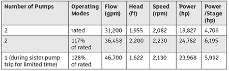
When unit-B runs at 2,082 rotations per minute (rpm) and flow of around 31,000 gpm, the power through the pumps will be between 18,000 to 19,000 hp, while at 2,230 rpm and flow of ~46,000 gpm, the power through the pumps will be ~28,000 hp. This indicates high energy for each impeller, approximately 7,000 hp. As a result, the impellers will be subjected to higher stresses, which is a contributing factor that will push the impellers beyond their material capability. Unit-B ran for longer periods at high flow rates than unit-A. As per the pump data sheet and performance curve, the pump should be designed for three points (Image 9). The pump second-stage original material 316 SS could not handle such stresses caused by pressure pulsation.
It was recommended to restrict the pump operation as per API 610 preferred operating range (70% to 110%) of rated flow at different speeds by adjusting pump control configuration to avoid subjecting the impellers to high stresses.
Impeller Wear Ring Looseness: Unit-B
The unit-B impeller wear rings of both second-stage impellers left-hand and right-hand came out due to inadequate shrink fit. The second-stage right-hand wear ring was split into pieces (Images 10 and 11) and impacted vanes leading edges.
Unit-B second-stage impeller left-hand wear ring came out due to inadequate shrink fit and was broken in one location. It became loose in places (Image 12). The axial set screws and tack welds added in 2012 were found broken.
Impeller Wear Ring Looseness: Unit-A
The unit-A second-stage left-hand impeller wear ring came out and broke into several pieces. These pieces went through the impeller and caused impact damage to vanes leading edges (Image 13).
The issue of eye wear rings coming out was experienced in both units in 2012 and was due to large and heavy rings, inadequate shrink fit and suction pressure surges. In 2012, both pumps experienced high suction pressures and surges.
In 2013, it was recommended to replace them with integral wear rings with the DLD process; the material used was tungsten carbide. In addition, the failed rings did not lead to vane damage as each failure was isolated from the other.
Process data trend of unit-B showed high suction fluctuating from 40 psig to 300 psig, and huge surges before failure as shown in Image 14.
Cavitation Damage of First-Stage Impellers: Unit-B
Unit-B first-stage impellers left-hand and right-hand have heavy cavitation damage on all vanes (Image 15). The cavitation damage was more than that in 2012 due to a greater number of hours in operation.
The pump ran after last overhauls in 2012 to 2013 approximately five to six years of successful operation with vane thickness loss of less than 30% (requirement by 31-SAMSS-04 is 40,000 hours with vane thickness less than 75%).
The existing vane thickness after cavitation erosion was within acceptance criteria. The first-stage impellers were of original design 316 SS. The cavitation damages were welded and dressed up. They were installed in the unit-B rotor on an expedited basis to meet production requirements and ran successfully.
In a nutshell, the net positive suction head available (NPSHa) exceeded the NPSH required (NPSHr).
Cavitation Damage of First-Stage Impellers: Unit-A
Unit-A first-stage right-hand and left-hand experienced cavitation erosion damage more than that in 2012 but was still acceptable as shown in Image 16. It was welded and dressed up.
Impellers Bore Interference Fit
In 2012, a pump vendor conducted stress analysis of a second-stage impeller and concluded that the cracking in the leading edge was partially due to high bore to shaft interference fit 0.003 inch to 0.005 inch (Images 17 and 18). It was recommended to reduce the second-stage impellers bore to shaft interference fit from the range of 0.003 inch to 0.005 inch to 0.001 inch to 0.003 inch. The reduction of interference fit, combined with the higher strength super duplex impeller material, increased the margin between the actual stress in the impeller vanes and the yield stress of the impeller.
The new super duplex impellers from the OEM were supplied with recessed bore to reduce the stresses.
Root Cause of Failure
Below are the main root causes of the failure modes:
- The root cause of the second-stage impeller failure was due to high-pressure pulsation that subjected the impellers to stress beyond the original material (stainless steel 316) tensile strength.
- The root cause of the second-stage impeller wear rings coming out was due to large and heavy rings, inadequate shrink fit and suction pressure surges.
- The root cause of the first-stage impeller cavitation was due to off-design operation, high flow and low suction pressure for short periods. The NPSH margin at average flow rates was verified and found adequate. The damage was acceptable and met the 40,000 hours criteria in accordance with internal pump standards. The damage was repairable by welding and dressing up.
Recommendations
- Upgrade both second-stage impellers with super duplex ASTM A890 grade 5A type CE3 MN to improve the material strength.
- Operate the pumps within the API 610 preferred range of 70% to 110% of rated flow and speed shown in Image 1 to eliminate high power per stage and excessive stress on the impellers’ material. The control system should be configured to operate the pump between 70% to 120% of BEP at different speeds.
- Upgrade both first- and second-stage impellers with integral wear rings with DLD tungsten carbide to eliminate wear ring coming out and consequential damages. Existing impellers that are equipped with removable wear rings shall be secured with six screws and six welds (2 inches long).
- During future repair, do not mix-match second-stage impellers, since the second stage is upgraded with new material and more thickness, and the first stage with more thickness only.
