

In the March 2025 edition of Pumps & Systems magazine, an article titled “3 Considerations for Dry Gas Mechanical Seals vs. Liquid Mechanical Seals” attempted to identify advantages between these technologies. The conclusions drawn in that article regarding dry seals in pumps were not entirely accurate. The assumptions appear based on compressor dry gas seal technology designs, which are much different than dry gas seals used in process pumps. Dry gas seal technology has been utilized for well over 30 years in process pumps to achieve reliability and emissions goals for end users. This article will provide an overview of the application of gas seal technology for process pumps and its advantages.
Overview
Considering evolving environmental regulations, gas seal technology remains crucial for safety, reliability and sustainability in pumps, mixers and rotating equipment. Dry gas face lubrication ensures product purity and zero emissions, offering significant benefits. This technology has helped avoid undesirable emissions for years. Pollution control efforts have been mandated, and a level of effort has been and continues to be defined to limit emissions. As an example, a population estimate of noncontacting pump gas seals sold into the market over the past 31 years of 105,000 units in these applications is reasonable, as is an average 6-year operating life. This would indicate 272.2 million pounds (about 123.4 kilograms [kg]) of toxic release potential avoided with zero emissions technology.
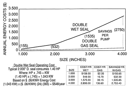
Maximum Achievable Control Technologies (MACT) are central to these efforts. The Air Quality Management District (AQMD) in California estimates annual emissions of chemical/refining process pumps at 432 pounds, with updated Environmental Protection Agency (EPA) values suggesting 2,200 pounds per pump. In 1993, cost savings from this technology were validated at $500 per seal at 6 cents per kilowatt hour (kWh). Today, with energy costs at 10-16 cents/kWh, savings are $1,350 per seal per year. Image 1 compares the energy costs of gas seals and wet seal systems. These findings were covered in a 1994 Pump Symposium paper by Wasser, Sailer, et al. Similar comparisons can be made using the Life Cycle Cost Estimator at fluidsealing.com.
There are many different seal arrangements used today to reduce emissions. The list below ranks the arrangements in their ability to control emissions on rotating equipment from best to worst:
- Dual-pressurized, non-contacting gas seal
- Dual-pressurized liquid seal
- Dual-unpressurized seal with liquid containment seal
- Dual-unpressurized seal with dry-running, contacting/non-contacting containment seal
- Single seal with bushing
- Single seal
- Packing
The Evolution of Seals in Fluid Pumping
Early fluid pumping used fiber packing with wax or graphite to seal shaft leakage, but it generated heat and shortened service life. To improve lubrication and cooling, a perforated lantern ring was used. Adequate lubrication extends the life of sliding surfaces. These limitations led to the development of end face mechanical shaft seals, which require effective lubrication.
Tribology and fluid development have optimized lubrication for seals. Manufacturers created face designs to resist distortion and wear under pressure. Some designs distort favorably to enhance lubrication and minimize wear. Lapped and polished seal faces resist pressure, friction and wear. Various seal arrangements provide process containment with optimal face lubrication. Liquid seal face lubrication is preferred for its performance under pressure, resistance to friction and heat and compatibility with process fluids.
Spiral Groove Technology
Evert Muijderman, a Dutch professor of tribology, pioneered the use of repetitive groove patterns in ultra centrifuges. This technology evolved from bearing design to end face mechanical seals, providing noncontacting seals for pumps over 30 years ago.
The noncontacting feature is achieved by a face pattern on one seal face, which lifts off as the shaft rotates, eliminating friction. An inert gas, like nitrogen, is used as a barrier at 20-30 pounds per square inch (psi) above process pressure. Spiral grooves effectively achieve face separation for noncontacting operations, resulting in zero emissions.
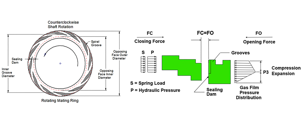
Spiral grooves are logarithmic spirals machined into one seal face, typically the harder material. As the shaft rotates, gas is forced into the grooves, compressed by viscous shearing and expanded at the sealing dam, separating the faces by a few micrometers. Hydrostatic liftoff during shutdown reduces face damage. The first spiral grooves for pumps had stationary unidirectional grooves at the outer diameter of the stationary face.
The challenge for gas seals in process pumps was achieving liftoff at lower velocities than turbo compressors, which run at over 10,000 rotations per minute (rpm). Process pumps run at 1,200-3,600 rpm, requiring stronger materials, advanced groove designs and reduced spring loads and O-ring friction to enhance face separation.
Applications of Spiral Groove Technology
The first noncontacting, dry running seals for pumps were used at a polymer manufacturer in 1992, ensuring product purity and environmental protection. Over 30 years, spiral groove technology has been applied to pumps, mixers, fans and blowers, handling various speeds, pressures, temperatures and solids concentrations.
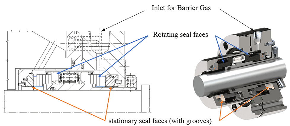
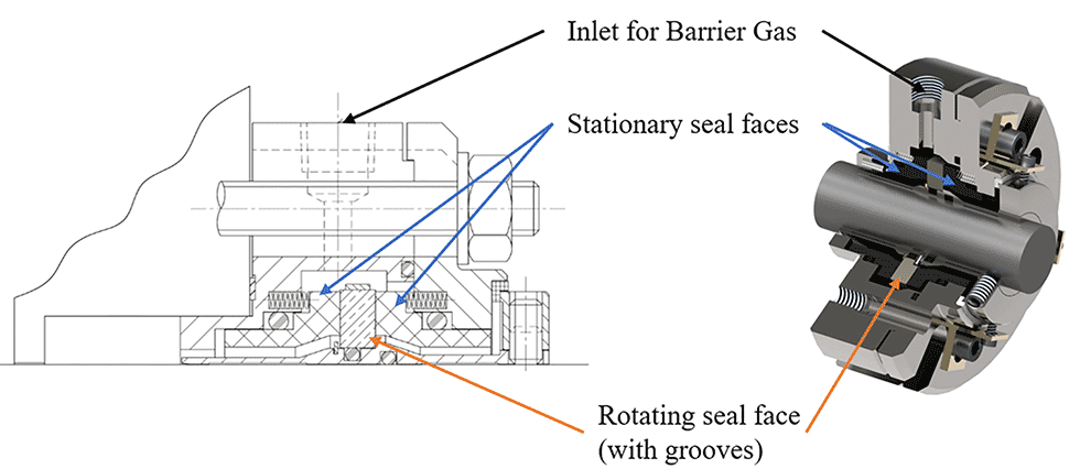
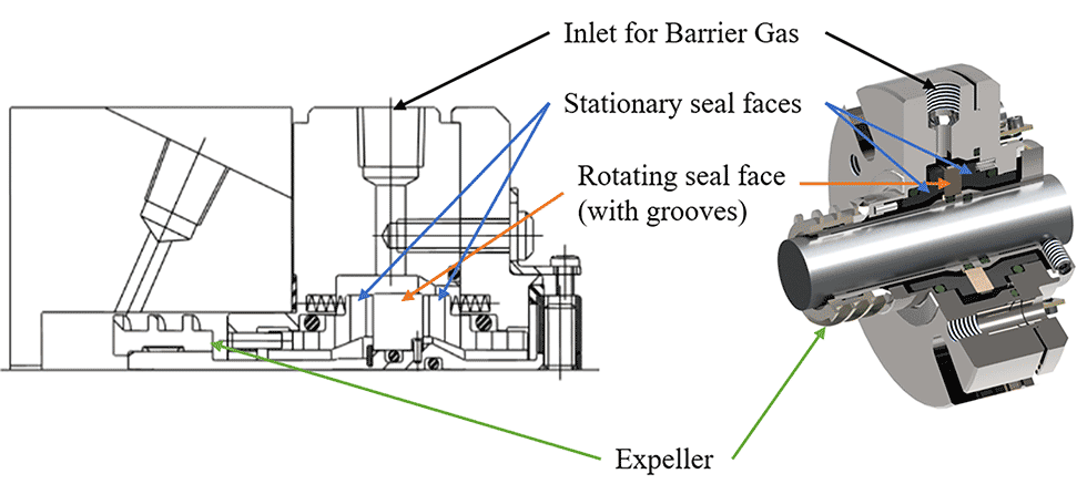
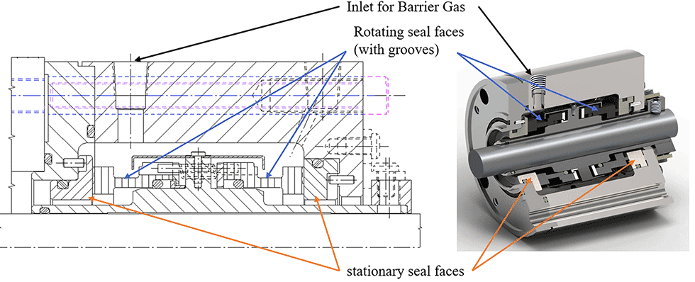
Image 3 shows the first seal installed on a big bore centrifugal pump. Image 4 illustrates a noncontacting gas seal for American National Standards Institute (ANSI) and Deutsches Institut für Normung (DIN) standard bore chambers, using a single mating ring with spiral grooves and an inert barrier gas. Image 5 shows the same seal with a solids handling expeller device, effective for processes with up to 30% solids.
The technology was later applied to mixers and vessels, ensuring product purity in pharmaceutical, food processing and petrochemical industries. Designers developed spiral grooves in carbon primary rings to handle slow speeds and high-shaft runout, generating hydrodynamic and hydrostatic lift.
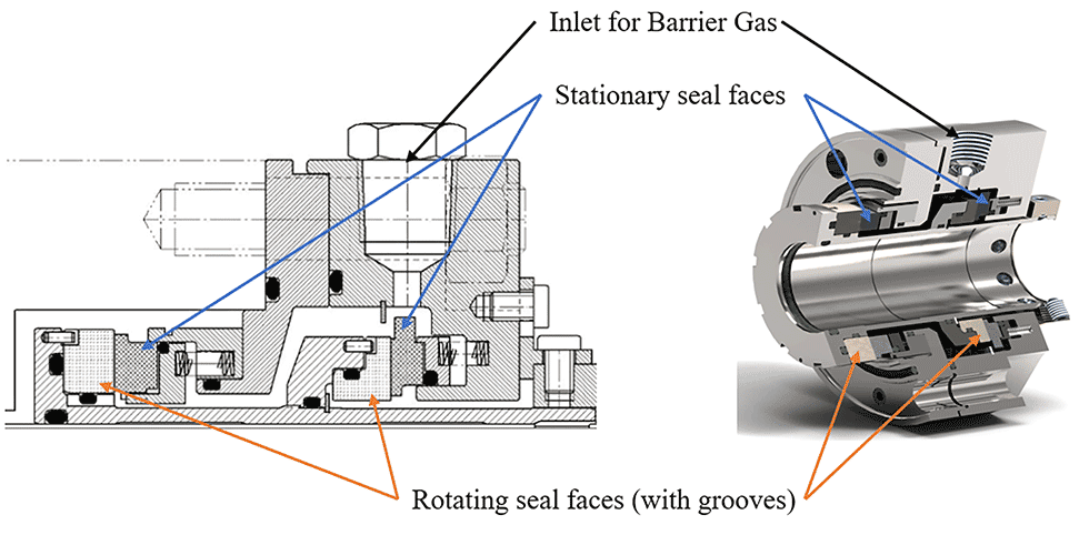
After 20 years, the seal was redesigned for higher pressure applications and processes with solids. Image 7 shows a seal for big bore ANSI pumps, incorporating a solids-handling feature and improved performance.
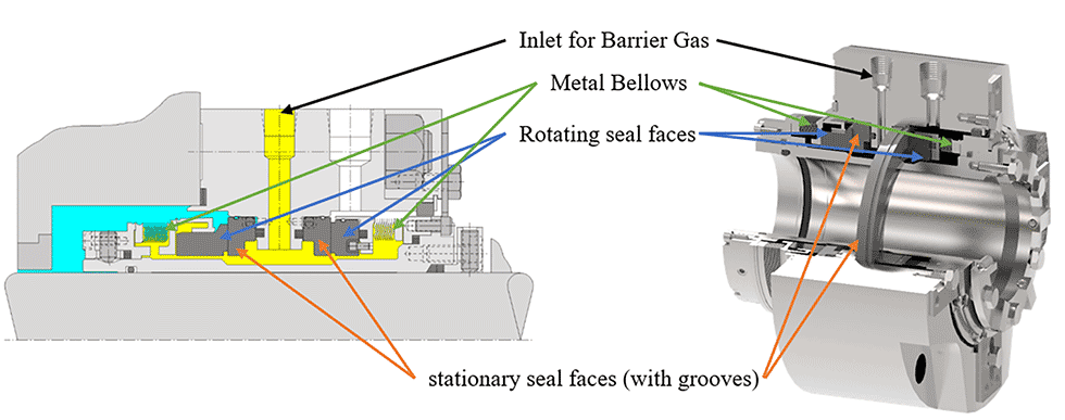
The latest development is a high-temperature gas seal for applications up to 800 F (425 C). Image 8 shows a metal bellows seal, providing spring force, accommodating axial movement and transmitting torque. The hermetic bellows act as a dynamic seal, allowing for a wide choice of secondary seals. The seal is pressure balanced, capable of reverse pressure operation to prevent fluid release.
Gas Seal Support Systems
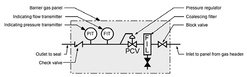
All pressurized dual seal arrangements have a barrier fluid at a pressure greater than the process pressure being sealed. Dual gas seals differ from other pressurized multiple seal arrangements in that they do not have circulation of a liquid between the seals but rely upon an external source of inert gas to pressurize the seal cavity provided by the seal cartridge. The piping plan designation for dual pressurized gas seals in API 682 is Piping Plan 74. A basic schematic of Piping Plan 74 is shown below in Image 9.
The sealing system works by allowing fluid to flow from high- to low-pressure areas. Mechanical seals use seal faces and O-rings to minimize leakage, requiring a small clearance to prevent heat damage. This clearance lets high-pressure fluid pass to a lower-pressure area, typically the atmosphere. Dry gas barrier seals use regulated barrier gas at 30-50 psi above process pressure to seal the process fluid from the atmosphere.
Nitrogen is most often used as the barrier gas due to its compatibility and economic factors. It is usually supplied from a pressurized nitrogen line or, less reliably, from nitrogen bottles. If nitrogen pressure is insufficient, a gas pressure booster can be used.
The control system must regulate pressure, filter the barrier gas and monitor pressure and flow to prevent overpressure. Filtration to less than 1 micron is needed due to the small seal face clearance. Flow meters help monitor gas flow, with API Plan 74 panels using transmitters for continuous monitoring of seal health. The key factor is monitoring the barrier pressure supplied to the seal.
Gas Seal Advantages to the End User
While gas seal technology in pumps offers benefits, there are misconceptions about wet vs. dry dual pressurized seal configurations. Wet pressurized seals use liquid barrier fluids (API Plans 53A/B/C and 54) for lubrication and cooling, while dry pressurized seals use gas, requiring minimal conditioning.
Cost of ownership: Both wet and dry seal cartridges have similar base costs. Wet seals need utilities like nitrogen, clean fluid, wiring, cooling water and power for pumps and fans. Dry seals mainly need nitrogen and wiring, with power only for nitrogen amplifiers if needed.
Barrier fluid compatibility: Wet seals require compatible liquid barrier fluids, which can affect process quality. Dry seals use nitrogen, which is inert and usually poses no issues.
System monitoring and maintenance: Wet seals need regular barrier fluid replenishment and heat exchanger maintenance. Dry seals require monitoring of barrier pressure, with backup nitrogen sources for reliability. High flow in dry seals needs investigation but can often continue operating if barrier pressure is maintained.
Seal face generated heat and horsepower consumption: Wet seal systems consume more horsepower and generate more heat compared to gas seals. Gas seals have minimal temperature rise and lower energy consumption. Wet seals can consume about 1,300 kWh/year, releasing 2 tons of carbon dioxide (CO2), while gas seals use only 350 kWh/year, releasing 0.54 tons of CO2. For an estimated population of roughly 105,000 gas seals operating for an average of 6 years per seal, the kWh saved by noncontacting dry gas seals is 8.6 million kWh. This sum is nearly equal to the kWh usage for the houses in the city of Houston, Texas.
Support system proximity requirements: Gas seal systems offer flexible mounting locations for control and monitoring instruments, unlike wet seals, which need proximity to minimize piping losses. Gas seals use nitrogen gas, which does not circulate, allowing the panel to be placed away from the equipment. This flexibility is advantageous for retrofit applications, ensuring maintenance accessibility.
The development and acceptance of noncontacting, dry gas-lubricated sealing technology has resulted in significant environmental advantages when compared to conventional liquid-lubricated, contacting face seals. The technology enables process pumps to operate with zero fugitive emissions over the life of the seal, resulting in many thousands of tons of toxic waste containment worldwide, while requiring zero gallons of cooling water. The global population of noncontacting, gas-lubricated seals has been responsible for a reduction in parasitic horsepower losses and significant energy savings. This low energy sealing results in a consistent annual reduction in CO2 emissions of about 2 tons per year, per pump. Finally, improvements in mean time between repairs (MTBR) and reliability very often create a standalone cost of ownership advantage compared to contacting wet seals.
Like any technology advancement, these seals must be applied correctly and with insight. Noncontacting, dry gas lubricated sealing technology continues to be a viable option for meeting emissions targets and reliability objectives.
We invite your suggestions for article topics as well as questions on sealing issues so we can better respond to the needs of the industry. Please direct your suggestions and questions to sealingsensequestions@fluidsealing.com.
For more information on dry gas seals, visit pumpsandsystems.com/tags/dry-gas-seals.
