

Some industry professionals have voiced concerns relating to the use of rubber expansion joints in pump piping applications. One recent claim cited installation misalignment and the expansion joint’s stiffness or spring rate as the reason for increased vibration levels across the system and more force being applied on the pump.
While every pumping system is different, it is more likely that the pressure thrust force from an unrestrained expansion joint would impose far more force and adversely affect pump performance, as opposed to a few hundred pounds of spring rate load.
It is important to understand that unless the rods of the control unit are tied snug tight, the expansion joint could still impose a potentially damaging pressure thrust force on the pump. This point is commonly missed and may explain why some hastily feel the solution is to eliminate expansion joints, increase the rigidity of the piping system and tighten installation tolerances.
When assessing pump piping applications, it may be helpful to look at several alternative solutions for the same application and compare the different axial and lateral end load conditions. Alternative solutions can include the incorporation of anchors, rigid pipe loops, traditional restrained or unrestrained rubber expansion joints, as well as more advanced rubber expansion joint arrangements.
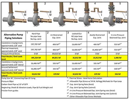
In Image 1, five alternatives are presented for a 36-inch diameter pump application with 25 feet axial run of carbon steel pipe under 90 pounds per square inch (psi) with temperature fluctuations of 50 F. Considerations include 1/8-inch thermal pipe movement, 1/8-inch axial and lateral installation misalignment, as well as 1/8-inch anticipated ground settlement.
In this simplified assessment each solution will restrain the imposing loads and displacements, each with different end loads.
1. Incorporating a main anchor near the pump
This anchored pipe solution is problematic because it directs potentially damaging loads and displacements from that section of piping back toward the pump. The carbon steel pipe will carry the full pressure thrust force in tension, but the pipe stress from thermal and misalignment displacements is tremendous. The axial end load can be determined using the axial force calculation for thermal stress, while assuming the lateral end loads can be calculated by other allowable pipe stress methods due to its relatively long leg length. The end loads for Solution 1 extend to a staggering 395,564 pounds of force (lbf) axially and 32,812 lbf laterally.
2. Incorporating an unrestrained expansion joint installed between a main anchor and the pump
This anchored pipe solution is also problematic because it directs potentially damaging pressure thrust force from that section of piping back toward the pump. The expansion joint (Image 2) absorbs the pipe stress from the thermal and misalignment displacement well; however, the pressure thrust force is quite large. The axial end load can be calculated as the sum of the pressure thrust force and the axial spring rate load of the rubber expansion joint. The lateral end loads can be calculated as the lateral spring rate load of the rubber expansion joint. The end loads for Solution 2 extend to an imposing 89,831 lbf axially and 670 lbf laterally.
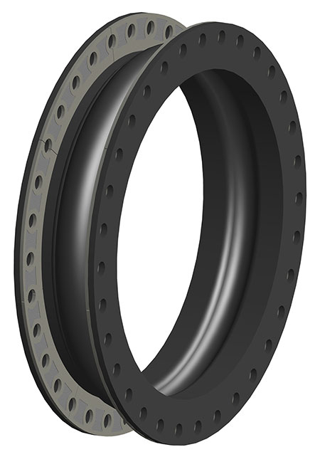 IMAGE 2: Unrestrained expansion joint
3. Incorporating a rigid pipe loop installed against the pump
This unanchored pipe solution works well when there are no space restrictions and the pipe loop can freely move away from the pump. The carbon steel pipe will carry the full pressure thrust force in tension. While the pipe stress from thermal and misalignment are within allowable pipe stress, they are still significant. The axial and lateral end load can be calculated using the M.W. Kellogg method for pipe loops. The end load for Solution 3 extends to a less imposing 32,812 lbf axially and 32,812 lbf laterally.
4. Incorporating a restrained rubber expansion joint installed between a rigid pipe loop and the pump
This unanchored pipe solution often works better because the restrained expansion joint absorbs the misalignment and ground settlement displacements while the pipe loop absorbs the axial thermal displacement. All components are restrained and will carry the full pressure thrust force in tension and it does not transfer that load onto the system’s ends. The misalignment and ground settlement load can be calculated as the spring rate load of the rubber expansion joint. The axial terminal end load can be calculated using the M.W. Kellogg method for pipe loops. The end load for Solution 4 extends to a more manageable 16,812 lbf axially and 670 lbf laterally.
5. Incorporating an inline pressure balanced rubber expansion joint installed between an intermediate anchor and the pump
This is the only effective solution for directly absorbing axial thermal movements with continual self-restraint of the pressure thrust forces. This advanced rubber expansion joint arrangement consists of tie devices interconnecting its main joint section to its opposing balancing joint section (Image 3). This is an optimal solution when there are load limitations on the pump and there is a high value placed on reducing the system footprint, as well as saving material and energy costs.
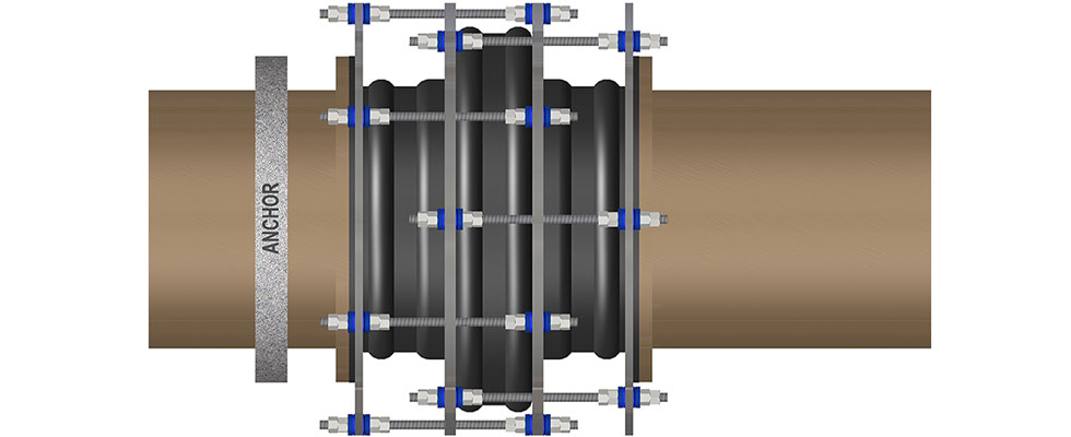
The axial and lateral end loads can be calculated as the sum of the spring rate load of the inline pressure balanced rubber expansion joint. The end load for Solution 5 extends to a manageable 1,406 lbf axially and 336 lbf laterally.
When end loads on pump piping are a concern, optimal solutions are neither to increase rigidity into the piping system nor ignore the imposing pressure thrust forces as an effect of some expansion joint arrangements, but rather to incorporate axially restrained (tied) or more advanced rubber expansion joint arrangements.
We invite your suggestions for article topics as well as questions on sealing issues so we can better respond to the needs of the industry. Please direct your suggestions and questions to sealingsensequestions@fluidsealing.com.
Read more FSA Sealing Sense articles by clicking here.
