

In last month’s column (read it here), I began offering pump startup commissioning advice and procedures. As noted, I believe what most folks are actually looking for is the abridged Cliffs Notes version. Nevertheless, there are a few basic steps and overlooked details that, no matter the pump type or application, need to be covered. I started to explain those steps and details in Part 1 of this column. Here is Part 2.
Other Considerations
In no particular order, here is a list of other checks and action steps that are frequently overlooked when starting the pump.
Safety always has to be first and the prime directive. Please realize you could be working with pressurized systems that can be very hot, contain acid and start automatically. You are also standing next to rotating equipment that will unforgivably reach out, grab you and pull you in.
Wherever you are starting the equipment there is almost a 99 percent chance that the owner has some procedures that must be followed.
The most frequent oversight I witness is that the operating manual is cast aside and a long list of incorrect assumptions is formed that includes things that the factory must have done—but they did not. I have written many columns on this subject alone, but you must understand that no industrial pump is “plug and play.”
A simple check is to rotate the pump by hand. The pump should turn freely with no binding/rubbing. Large pumps may require added torque due to inertia that you can overcome with a strap wrench (be careful how and where the wrench is applied to preclude shaft damage).
Rotating by hand should be done after the lubrication is addressed, but before the seal is set. Also, it is much easier before the coupling is assembled.
It is implicit that the unit system must be locked out and tagged out.
Never rotate the pump under power without completing a rotational direction check on the uncoupled driver first. I also recommend a witness and documentation. Incorrect rotation is probably the second most frequent mistake I witness.
Unfortunately, new systems typically have abundant dirt and debris in the lines from construction. It is prudent to install a temporary commissioning strainer on the suction line. The strainer must have a cross-sectional area to allow proper flow and not create NPSH margin issues. The strainer must have some means of measuring the differential pressure across itself, otherwise you won’t know when it is clogged.
Pump systems with long and empty discharge lines will present issues for initial startup; as the line is filling with liquid, there is little to no resistance for the pump and so it will “run out” (to the right) on the curve. You can introduce temporary faux resistance by closing partially on the discharge valve. There is also the increased risk of water hammer and associated damage when the system does fill.
Before the pump is started you should know what flow and pressure to expect on the instrumentation and, oh yes, you need instrumentation. Also, know ahead of time what will be the expected amp reading, frequency (if using a variable frequency drive [VFD]) and perhaps the watt or power readings. I like to bring my own strobe-tachometer, vibration probe and infrared digital thermometer in the event the facility does not have this type of equipment. (Note: You will typically need permission and many facilities will not allow the use of personal equipment.)
Prior to starting the pump ask, is the mechanical seal support system online? This is especially important on API seal pipe plans 21/23/32/41/52/53/54/and 62.
For pumps that use packing in the stuffing box, check to ensure if there should be a flush line and, if so, is it connected to a clean water source? Also check for adequate pressure (flow) to the stuffing box. It is good practice to turn the flush water on prior to opening the suction and discharge valves on the pump. Check with the pump and/or packing supplier for the proper packing leakage rates that will vary with the liquid temperature and its other physical properties, shaft speed and size.
If you can’t find a reliable answer for your application, go with 10 drops per minute per inch of shaft diameter. I typically go with a more liberal 30 to 55 drops per minute regardless of diameter on the initial break-in period.
Make the gland adjustments in small increments, meaning one “flat” per adjustment on each gland nut, and space the adjustments out over 15 to 30 minute increments. The key to proper packing adjustment is patience. Consult with the “Fluid Sealing Association Technical Manual 4th Edition Compression Packing” for more.
You should use all of your senses when starting pumps or any equipment. Look for sparks, smoke and things rubbing that should not be—such as an improperly set bearing isolator or flinger. Listen for the popping of vapor bubbles in the impeller or a squealing mechanical seal that is starving for lubrication. Smell that? Packing is not supposed to smoke. Can you feel the deck and/or the pipe vibrate because the pump is coming off the base due to imbalance or cavitation? Know that you are not at Disney World on an E Coupon—this is the real world with expensive equipment that can crash, burn and hurt you and/or others.
Always minimize the time the pump will be operating at or near minimum flow areas (left side of the curve). Just as important is to not allow the pump to operate at the far right of the curve.
Avoid thermal shock issues if you are pumping something that is hot (above 200 F to 300 F, 93 C to 149 C)—warm-up procedures should be followed prior to startup. Large pumps will likely have minimum and maximum allowable rates of heat up and cool down. Many multistage pumps will require a warm-up procedure that also requires slow rotation on turning gear (aka, jacking gear) for some specified length of time or preordained temperature differential. Remove the pump from turning gear prior to startup. The valve lineup procedure will also include balance drum, warm-up and bypass lines.
Bearing temperatures (or the oil temperature) should be closely monitored on startup. Do not use your hand to feel for the temperature as it is not a precise method and, more importantly, most people will feel a bearing housing at 120 F (49 C) and think that it is really hot. It is not uncommon for bearing or oil temperature to approach 175 F or 180 F (80 C or 82 C). The important parameter to watch is the rate of change in temperature. Fast climbing temperatures are a red flag, and I suggest shutting the unit down and investigating the root cause. Where the temperature is measured is also important; a thermocouple inserted in the bearing is more indicative and timely than bearing oil sump or return path temperatures.
Frequent motor starts often occur during commissioning processes. Be aware of the allowable number of motor starts per unit of time for your motor—refer to National Electrical Manufacturers Association (NEMA) and/or the manufacturer for specifics. Typically the larger the motor and the fewer number of poles will result in a reduced number of starts allowed.
Discharge Valve Position
I am frequently asked: Should the discharge valve be open or closed when
the pump is started? My answer is it depends, but regardless, the suction valve better be open. First things first—let me state that if you are a visitor to a client facility, you should never supersede their operating procedures.
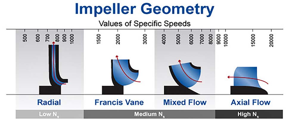
Next, let’s look at the impeller. There are many things to consider, but the primary question we want to answer today is: What is the geometry of the impeller? From that shape we will determine the range of specific speed (Ns). OK, I may have lost you now because I used the nerdy “specific speed” term, but let me explain. For today’s purpose, let’s focus on the directional path of the liquid and specifically how it enters and exits the impeller. Ns is a predictive indicator for the shape of the curves for head, power and efficiency.
Low Ns
If the liquid enters the impeller on a path parallel with the shaft centerline and exits the impeller at an angle 90 degrees to the shaft centerline (at a right angle) then the impeller is in the low Ns range.
Medium Ns
If the liquid enters the impeller on a path parallel with the shaft centerline and
exits somewhere close to a 45-degree
angle, then the impeller is in a medium Ns range. These are mixed flow or Francis vane-type impellers.
High Ns
If the liquid enters the impeller on a path parallel with the shaft centerline and exits in a path parallel to the shaft centerline, this is a high Ns impeller. This axial flow type of impeller would look similar to a boat or airplane propeller.
Plan B
Don’t know the NS of the impeller? Ask the equipment manufacturer.
For low NS pumps, the brake horsepower (BHP) required increases as you open the discharge valve and increase the flow rate; this is a direct relationship just as you would intuitively expect. For medium Ns pumps, the BHP curve and its maximum point moves back to the left some nominal amount. In the past, you may have not noticed this change. Axial flow pumps have a high Ns and the BHP is near its maximum point at the lower flow rates and actually reduces as the flow rate increases. Perhaps the opposite of what you would expect? Notice how the slope of the power graph also changes when the impeller design goes from low to high Ns.
Answering the Original Question
I recommend that the discharge valve be closed on the startup of low Ns pumps and to be open on high Ns pumps. Note: This is a “thumb rule,” and there are numerous caveats that can and will modify the answer. As follows:
1. If the low Ns pump is of any consequential size (flow, head and BHP), you may need to have the discharge valve slightly open to reduce the differential pressure (DP) across the valve. A high DP will prevent opening the valve and this step will minimize the effort to open the valve. Some systems will have a specific bypass line for this purpose. For pumps that have shafts with high shaft stiffness factors (L3/D4 is high), then you will want to keep the time operating on the left of curve as short as possible to ensure a longer seal and bearing life. Note that shaft stiffness factor values are counterintuitive and similar to golf scores. A high number is bad and a low number is good. Finally, note the curve shape; for example, curves that droop near shutoff can place the pump into a situation where it will hunt (oscillate). Consequently, you need to place the pump further out on the operating curve rather quickly.
2. Systems that have downstream pressure (from another source) with no check valves (or check valves that are leaking by) can force the pump to spin backwards when the discharge valve is open. Starting the pump while it is rotating backwards is an excellent method for breaking the shaft. Starting pumps that are in series or in parallel may often require procedures that are too detailed for this forum/column. See local procedures and/or contact the author.
3. If you are starting a pump that will operate in parallel with another pump(s), you need to consider check valve lift points and controlling instrumentation (proportional integral derivative [PID]). Also, when the first pump is started it can run out (far right) on its curve until the second (subsequent) pumps are started. This is too cumbersome to explain in this column.
4. Normally, high Ns pumps are started with the discharge valve open to reduce the electrical load and resultant stresses on the driver. In many cases the driver may not be adequately sized (on purpose) to handle the low flow power requirements and will trip offline.
Shutting Down
Normal procedures for shutting down pumps other than some high Ns types is to close the discharge valve first and then immediately secure the driver. This will mitigate unnecessary stress on the driver and, more importantly, it will reduce or entirely eliminate potential for water hammer issues.
For systems with variable speed drives there will probably be added steps and procedures. Care must be exercised as the driver frequency is turned down if the pump is being operating in parallel, and also due to minimum speed, check valve and system back pressure issues.
Final Pointers
Four last comments and tips to share:
Before you start the pump, know where and how to shut the unit down in case of an emergency.
During the startup evolution, never stand next to or in line with the motor fan or the coupling.
Have the phone number handy for your personal “phone-a-friend pump expert” for when things go wrong.
Always start with the end in mind.
