

Hydraulic mixing systems are becoming a viable alternative to traditional top- and side-entry mixers.
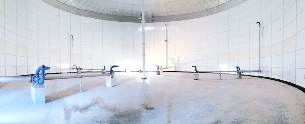
A hydraulic mixing system uses a centrifugal pump to agitate tanks containing chemicals, water, crude oil, slurries or other fluids. The centrifugal pump recirculates then discharges fluid through nozzles strategically placed inside the tank. High-velocity jets from the nozzles turn and rotate the tank contents, initiating a mixing process that features both top to bottom and circular fluid motion.
Circular fluid motion blends the contents of the tank, sweeps the tank floor, prevents buildup of solids and contributes to environmental uniformity. The top-to-bottom fluid motion generated by the nozzles helps maintain solids suspension.
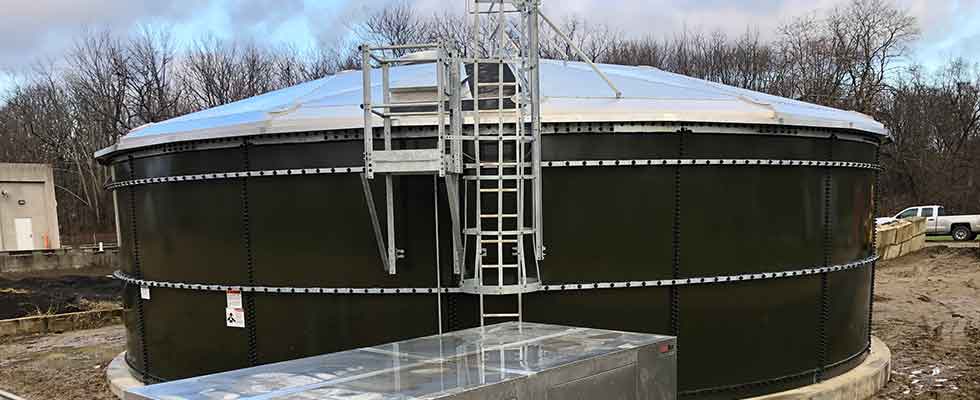
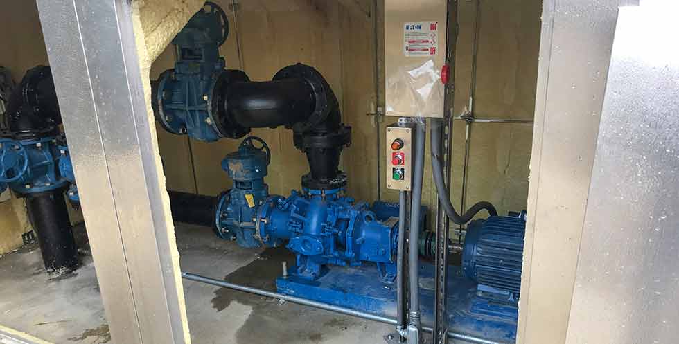
While hydraulic mixing might seem complex, a hydraulic mixing system is a relatively simple collection of equipment. The main components are a pump (which is set up outside the holding tank) and a series of nozzles. Unlike most traditional mixers, there are no rotating parts of any kind within tanks attached to a hydraulic mixing system. Some benefits offered by these systems include environmental uniformity, solids suspension, low maintenance, operational configurability and energy efficiency.
The fluid velocities generated in the hydraulic mixing process result in uniform solids suspension and distribution. Solid particles are prevented from settling and forming mounds. When used for chemical processing, a hydraulic mixing system creates a uniform environment and minimizes temperature, pH gradients and mixture stratification. Hydraulic mixing systems offer a high degree of operational configurability.
A variable frequency drive (VFD) can be configured with the recirculation pump for increased energy efficiency. The VFD allows plant operators to develop customized run cycles for the system to suit their specific application. The recirculation pump can be used for both transfer and mixing operations. Since these duties are combined, it may not be necessary to have a separate pump for transfer operations and a separate agitator for mixing operations.
The materials used to manufacture a hydraulic mixing system depend greatly on the fluid the system is intended to mix. For applications involving corrosive fluids, stainless steel would be the material of choice. If the fluid is abrasive, manufacturers are more likely to use hardened metals.
Nozzles can undergo various lining or heat treatment processes for further adhesion and abrasion protection. Nozzles and recirculation pumps are built for long-term service and do not require constant part replacements. Recirculation pumps can be selected per the requirements of the application: solid handling pumps for slurries, chemical processing American National Standards Institute (ANSI) pumps for chemicals, and American Petroleum Institute (API) rated centrifugal pumps for the crude oil.


While capable of a wide variety of tasks, it is best not to use a hydraulic system to mix highly viscous fluids. Any fluid that the pump finds too glutinous to handle should not be put through a hydraulic mixing process. A viscosity test should be conducted for suspect fluids to ensure they can be pumped by the centrifugal pump.
Beyond that, hydraulic mixing systems can tackle all manner of fluids. Hydraulic mixing systems can be used in applications involving water storage tanks, lime slurry tanks, sludge storage tanks, crude oil storage tanks, textile waste storage tanks, anaerobic digesters, etc.
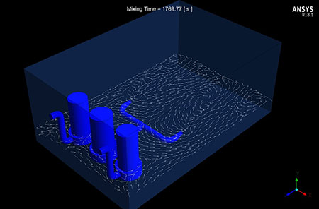
Computational fluid dynamics (CFD) is a key tool for validating hydraulic mixing system designs. It is used to customize the system to the user’s application requirements. Commercial CFD software can develop a meshed 3D model of a tank integrated with a hydraulic mixing system.
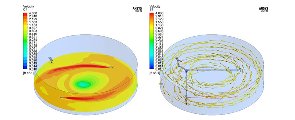
Fluid properties and simulation parameters are defined. The software uses this information to create a simulation of the proposed mixing regime. Velocity contours, velocity vectors, particle streamlines and iso-surfaces can be plotted onto the simulation. These tools are used to analyze the mixing regime and validate its effectiveness or whether further adjustments are required to ensure a proper mix. The simulation aids users in validating and understanding how the hydraulic mixing system will operate and whether it will meet their performance goals before the system is set up at the project site.
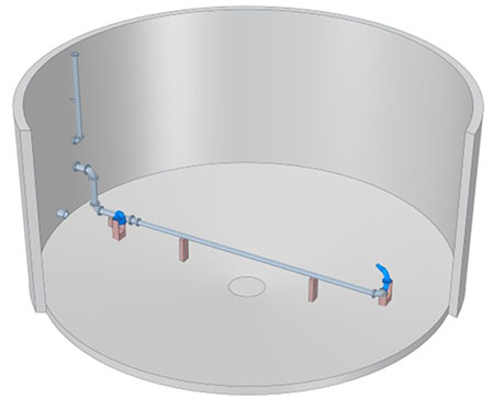
Hydraulic mixing systems are simple to put together. Setup entails little more than connecting the pump to suction and discharge piping, then connecting nozzles to the pipes. Typically, system manufacturers provide layout drawings and 3D models to the user to aid with optimal nozzle placements.
Simplicity is key to hydraulic mixing, a process that produces similar results to side and top entry mixing with potentially fewer worries.
