

Flow measurement of liquids is critical to many process operations to ensure product quality and regulatory compliance. Whether monitoring pump performance to maximize production quality, accurately dispense product, or avoid waste, not measuring the flow rate proves too costly. The data gathered from flow meters is invaluable for precise process control, improved quality and planned system maintenance.
How It All Started
The history of mechanical flow meters (positive displacement) dates to the 1800s when the water and gas industries used mechanical totalizers for billing purposes. Over a 50-year span between 1860 and 1910, municipal waterworks changed their position from stringently opposing the use of meters to requiring them on every tap to gather information on how much to bill customers and to improve their distribution systems.
While the use of turbine meters to measure gas flow dates to 1953, they were not widely used by the industry until 10 years later. Two developments facilitated their acceptance:
- Long-lasting bearing materials using ceramics and sapphire extended turbine life.
- The introduction of the hall effect sensor pickup enabled the detection of each turbine blade as it rotated with the flow medium for more precise measurement.
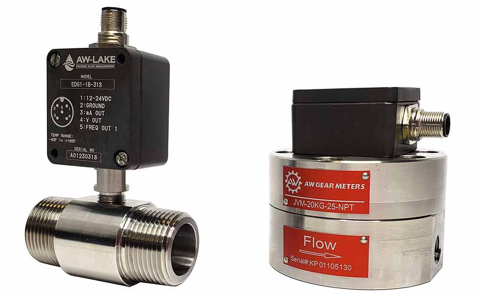
Positive displacement (PD) and turbine flow meters, when combined with these sensor pickups, emit a frequency pulse output proportional to material flow. Measuring frequency pulses is ideal for totalizing and batch processes as the programmable logic controller (PLC) must only count the number of pulses and multiply them times a K-factor (the number of pulses per volume).
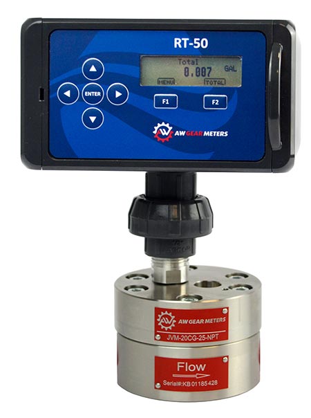 IMAGE 2: A battery-powered flow rate transmitter with Bluetooth capabilities enables operators to view readings and adjust the rate, total, reset, sleep mode or time on a smart device.
While even early evaluation electronics could accept these relatively high-frequency pulses (up to 10,000 hertz [Hz]), modern PLCs can still choke on high data input. While ideal for batch or totaling applications, the high data volume is overkill for flow rate measurement. High-speed counter input modules were designed to handle the high-pulse frequency inputs from positive displacement and turbine flow meter sensors.
For simple flow measurement, PLC programmers prefer analog inputs of various signal types (0-5 volts [V], 1-5 V, 1-19 V, and 4-20 milliampere [mA]). To provide this output, programmers must convert and scale the native pulse frequency from a PD or turbine meter to an analog signal in a digital to analog converter. Scaling was accomplished by setting digital switches in a converter and the PLC program. This is a somewhat difficult process prone to error that can cause havoc.
Typical PD & Turbine Applications
PD and turbine measurement applications vary widely. Primarily, OEMs and end users monitor and/or control a flow process, archive quality control data, fill containers, or batch-dispense materials into a mixture. Today’s OEM controllers can not only monitor a flow rate but also control the desired flow rate by using air piloted fluid regulators or proportioning valves and flow meters for feedback in a proportional-integral-derivative (PID) controlled process. One classic example is 2K (two-component) painting. Here, the controller regulates the flow rate of a resin (paint) as well as the flow rate of a catalyst in a fixed ratio. These systems know if either the resin or catalyst flow is off spec and can ensure the correct resin-to-catalyst ratio.
Flow meters paired with PLCs are commonly tasked to monitor flows of liquids and gases.
One example is monitoring the flow of cooling fluids used in machining processes. If flow rates drop too low, the machining process is stopped to prevent damage to expensive tooling.
Other plants are more concerned about incorporating data logging into a process. If a quality defect is detected, a forensic review determines if conditions were out of spec and troubleshoot the process, if necessary. Many users need flow data to accurately mix low viscosity liquids to create a product. Many of these batch applications use PD and turbine meters along with other control equipment to control the precise amount for each chemical to the batch.
Smart Sensors & Converters
Programmable smart electronics enable engineers to manipulate information gathered from flow meters in new ways while simplifying initial system setup. Previously, a knowledgeable tech or PLC programmer would set the conversion variables as part of the PLC program. While this step still happens to a degree, programmable digital electronics eliminate the need for high-speed counter inputs and complex analog scaling of digital-to-analog converters. It is even possible to eliminate both pulse and analog inputs altogether.
In one configuration, a flow sensor can communicate digitally using industry-standard MODBUS serial protocol.
Bluetooth embedded into the electronics enable flow meter monitoring and programming from a phone or tablet within range of the device. Smart transmitters often support local display of flow rate or total (Image 2) while also offering Bluetooth connectivity, which enables operators to view readings and adjust parameters on their mobile device without needing to use the device’s integrated buttons. Often, the mobile or PC-based applications are easier to navigate, saving time.
Electronics Simplify Flow Meter Setup
In addition to managing data, digital electronics simplify the meter setup. Embedded applications guide users throughout the setup process directly on their smartphone or laptop. The applications remove the need to convert meter variables to the desired flow units to prevent simple user errors. Instead of taking the time to convert a meter variable (K-factor) given in gallons per minute to liters per hour, smart electronics can provide instantaneous and precise conversions.
Electronics also improve linearization. Not all flow measurement is linear as the K-factor varies slightly at different flow rates. For best accuracy, multiple K-factors—one for each flow rate— are used when initially calibrating a meter at the factory. With an electronic’s app, multiple K-factors are entered directly into the smart sensor or frequency-to-analog converter. By removing these critical steps from the PLC and configuring this information via an app, manual errors and labor are reduced.
Smart sensors and converters can also automatically scale the meter variable to any desired unit of measure. Whether wanting data stored or transmitted in gallons per minute or cubic feet per second, the smart electronics can do so. For OEMs who want to program all systems the same way, the flow electronics can send the same scaled output (frequency or analog) to a control system for uniformity that alleviates problems associated with changing out spare parts with different meter variables.
Smart electronics can also verify that a system is reading information correctly. Digital electronics can force a frequency or analog output to ensure wiring is correct.
In the case of an analog signal, the electronics can calibrate a 20mA output to match a reading. Operators can calibrate by forcing the electronics to output 20mA and, then, enter the actual reading (20.3mA for example). The electronics will then calibrate to the system.
Although mechanical metering has not changed significantly over the last century, the use of smart electronics has expanded the amount and type of generated data and helps operators to better understand and use it for higher quality system performance, easier setup and timely maintenance.
