
Q. How are chemical metering pumps used in combined-cycle power plant applications?
A. Numerous applications in a combined-cycle power plant require the delivery of precisely metered quantities of chemicals. Chemical metering pumps are positive-displacement types (see Figure 6.16) and are designed for continuous operation.
One of the key applications is to deliver chemical solutions to control the amount of emissions. Natural-gas-fired, combined-cycle power plants produce approximately one half of the CO2 emissions and one third of the nitrogen oxides (NOx) produced by conventional power plants. They also eliminate sulfur dioxide emissions.
The combustion turbines in a combined-cycle plant produce low NOx and CO2 emissions. The heat recovery steam generator then uses a selective catalytic reduction scrubber system to reduce the NOx to a very low level (approximately 30 percent of a simple-cycle combustion turbine’s NOx emissions using similar technology). Some are as low as 10 percent of the simple-cycle emissions.
The scrubber system is engineered to treat a specific cubic feet per minute range of gas, within a specific temperature range. Further, the system is engineered to reduce the level of contaminants from a specific inlet concentration to a specific outlet concentration. Other typical metering pump applications include boiler feed, cooling tower feed, wastewater treatment, condensate treatment and feeding the makeup water system.
More information about the use of chemical metering pumps in combined-cycle power plants can be found in Power Plant Pumps: Guidelines for Application and Operation to Maximize Uptime, Availability, and Reliability.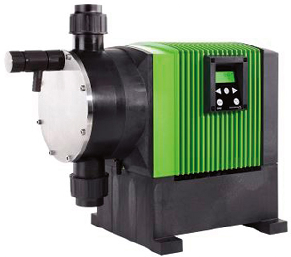
Figure 6.16. Chemical metering pump
Q. What kinds of boiler feed pumps are used in a typical 400-megawatt, combined-cycle
power plant?
A. No fixed rules are available for selecting the pump type for a boiler feed application. Pump selection depends on a combination of the manufacturer’s application experience and product offerings and the end user’s experience in maintainability and reliability. If the plant will be cycled instead of base loaded, then special consideration must be given to the use of a sufficiently robust and proven pump design.
Electric utilities favor the between-bearings pump arrangement for the highest level of reliability. For pressures up to approximately 1,800 psi (125 bar), typical boiler feed pumps include horizontal multistage ring-section (type BB4, see Figure 6.1) or axial split-case designs (type BB3), although in some applications there may be a preference for a double-case pump (type BB5).
For higher pressures, the boiler feed pump types used are usually multistage ring-section (type BB4) or double-case pumps (type BB5).
Some end users choose to give particular consideration to the main pump construction features. They include:
- Type BB4 ring-section and type BB5 double-case pump types both have radial sealing joints, which are geometrically simpler than an axial split-case pump sealing joint. The double-case pump has fewer sealing joints than the ring-section pump.
- Type BB3 axial split-case pumps and the axial split inner casing version of the type BB5 double-case pump allow for the entire assembled rotor to be removed and balanced as a unit. These rotors usually have opposed impeller arrangements that reduce the hydraulic thrust carried by the thrust bearing.
- The ring-section and double-case pump geometries inherently lend themselves to design for pressure containment. The double-case pump type has an integrally safer containment for pressures exceeding 3,600 psi (250 bar).
For more information about boiler feed pumps and their application in combined-cycle power plants see HI’s newest guidebook Power Plant Pumps: Guidelines for Application and Operation to Maximize Uptime, Availability, and Reliability.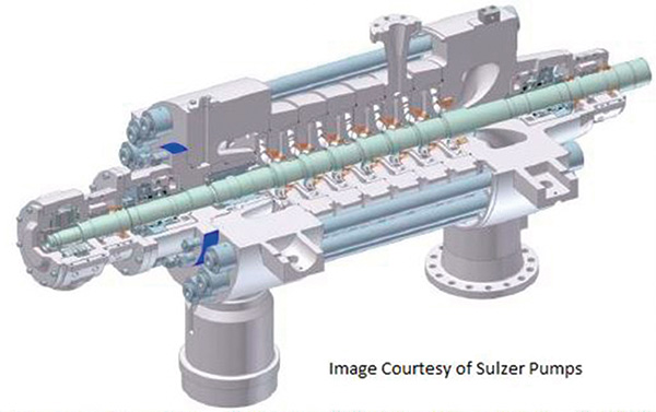
Figure 6.1. Three-dimensional view of multistage ring-section pump (BB4)
Q. What information is available about hydrostatic pressure tests for rotodynamic pumps?
A. ANSI/HI 14.6 contains information about this subject. According to this standard, all pressure-containing items of the rotodynamic pump will be hydrostatically pressure tested. The test’s purpose is to demonstrate the absence of leakage through pressure-containing walls of any item under test and from the joints formed by an assembly of items under test by imposing a defined pressure in excess of the rated pressure for which the item is supplied.
Pumps with double volutes, multiple stages and otherwise with internal separating walls that will be tested in segments should have a hydrostatic pressure test applied to each segment related to the operating conditions in the segment when the pump is working at its rated discharge pressure. Pressure-containing chambers that function independently should be tested separately without pressure being applied to any adjacent chamber.
The manufacturer will allow sufficient time during manufacturing for the test and the examination of all the items within the scope of ANSI/HI 14.6. The test may be carried out on an individual item or a subassembly as a group of items.
Normally, the hydrostatic pressure test is carried out after completion of machining and following nondestructive testing or after special leak tests are below a gauge pressure of 7.25 psi (50 kPa).
The hydrostatic pressure test is normally carried out using clean water at ambient temperature, with the addition of corrosion preventatives, wetting agents and organic growth inhibitors when necessary. The hydrostatic test pressure is calculated from a formula that considers the requirements of the pump specification, the allowable stress at ambient temperature and the allowable stress at operating temperature.
The test pressure will be maintained for a sufficient time to allow for the complete inspection of the item being tested and will also consider the pressure level in determining the test period. Shaft power is also considered.
The arrangements used to seal the chambers to be pressurized will be inspected for proper bolting and enclosure before applying the test pressure. The hydrostatic pressure will be steadily increased in a controlled manner until the test pressure is achieved. The test pressure is then held essentially constant for the duration of the test period.
Throughout this procedure, continuous observation will be maintained to detect any leakage. The test pressure should be maintained for a sufficient time to allow for the complete inspection of the item being tested.
Special attention should be given to thermoset parts. Because of the irreversible damage that can occur to the reinforcement of thermoset parts that are put under excessive pressure, hydrostatic test pressure shall be 1.1 times the rated pressure for those parts.
The manufacturer will verify through test records that adequate sampling was performed to prove that the parts can sustain the full hydrostatic test pressure calculated using the formula.
When a full hydrostatic test pressure on thermoset parts is requested, all parties should agree on the consequences of possible irreversible damage.
For more information about the test procedure and acceptance criteria for hydrostatic tests on rotodynamic pumps, see ANSI/HI 14.6 Rotodynamic Pumps for Hydraulic Performance Acceptance Tests.
