
Q. What considerations should be made when selecting the proper boiler feed pumps for a typical 400-megawatt, combined-cycle power plant?
A. The operating range of the plant compared to the operating range of the pump, as well as reliability considerations and first cost, will determine how many pumps are required. Large thermal power stations typically have two or three installed 50 percent boiler feedwater pumps.
The recommended margin of net positive suction head available (NPSHA) over net positive suction head required (NPSH3) for boiler feed pumps can be relatively high. This will depend on the rate of flow, the pump’s operating speed, whether the first-stage impeller is a single- or a double-suction type, and the pump’s expected operating range. The pump manufacturer will provide NPSH3 and margin recommendations to mitigate cavitation and provide long life of the first-stage impeller.
A key factor in pump selection for demanding boiler feed service is rotor hydraulic axial balance. Two types of rotor construction need to be considered:
- In-line (tandem) impellers (see Figures 6.2 through 6.4)
- Opposed (back-to-back) impellers (see Figure 6.6)
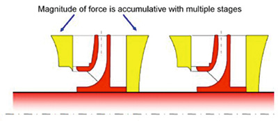 Figure 6.2. Hydraulic axial thrust
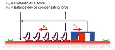 Figure 6.3. Compensation of axial thrust by a balance disk
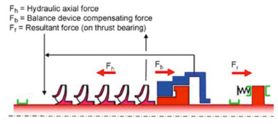 Figure 6.4. Compensation of axial thrust by a balance disk or a stepped balance drum together with a thrust bearing
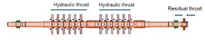 Figure 6.6. Opposed impeller design
With in-line impellers, the hydraulic axial thrust of the impellers is usually countered by a balancing device—either a balance disk or a balance drum—or sometimes a combination of both. The advantages of a balance disk design may include reduced internal recirculation (better volumetric efficiency) and the disk’s ability to compensate for wear and the amount of thrust that requires balancing. The disk is referred to as a self-compensating balancing device and may be used to exclude an axial thrust bearing in certain designs, reducing initial cost and simplifying rotor construction and assembly. The balance drum does not compensate for changes in thrust and typically exhibits more internal recirculation losses than a balance disk.
The advantage of the balance drum compared to the balance disk is in the openness of its running clearance. For systems in which severe upsets may occur or in which foreign material is continuously present, balance drums (with their larger running clearances) may prove less sensitive (less susceptible to damage) than balance disks.
For more information about boiler feed pumps for combined-cycle power plant use, see Power Plant Pumps: Guidelines for Application and Operation to Maximize Uptime, Availability, and Reliability.
Q. I’ve heard that residual mechanical unbalance of rotating parts is one factor that affects rotodynamic pump vibration. What information is available regarding this topic?
A. High levels of residual unbalance in rotating parts can generate high unbalance forces, resulting in excessive bearing and shaft loading and inducing high levels of vibration. Balancing methods and residual unbalance limits for impellers should be applied when analyzing pump vibration.
Depending on component geometry, performing a single-plane spin balance may be satisfactory. Components are typically single-plane balanced if the ratio of the diameter to the width (D/b) is 6 or greater. Two-plane (or dynamic) balancing is typically performed otherwise. Balancing-machine sensitivity shall be adequate for the part to be balanced. This means that the machine is capable of measuring unbalanced levels to one tenth of the maximum residual unbalance allowed by the balance quality grade selected for the component being balanced. Balance machines shall be calibrated as recommended by their manufacturer. When specified, calibration shall be done just prior to balancing.
The practice of component balancing is appropriate for a large proportion of rotodynamic pump types that can be proven to meet the specified vibration performance criteria while using clearance fits between the rotating component parts and the shaft. Residual unbalance grades are then determined to meet vibration performance acceptance levels while also considering the mass eccentricity effects caused by clearance fits and the resulting component runout. Clearance fits are preferred and used whenever possible to facilitate pump assembly and disassembly.
However, many pump types and applications require the use of shrink fits and the performance of a supplementary two-plane (dynamic) balance on the complete rotating assembly to meet the specified vibration performance criteria. In these instances, the manufacturer and the purchaser should agree on the appropriate residual unbalance grade.
For more information about rotodynamic pump vibration, see ANSI/HI 9.6.4 Rotodynamic Pumps for Vibration Measurements and Allowable Values.
Q. What should be considered when designing a piping system for process pumps?
A. Many pipe specifications have sizing rules to aid in the selection of the optimum pipe diameter. The sizing rules can be based on achieving an optimum average fluid velocity in a pipe run for the design flow rate or a specific pressure drop per unit of pipe length. The pipe run sizing rules are trade-offs by:
- Choosing a small pipe diameter to minimize construction cost
- Choosing a large pipe diameter to minimize pipe run friction loss and pumping cost
The value for the optimum pipe diameter is based on the cost of the piping versus the cost of pumping power. If the pipe diameter is below the optimum diameter, then the cost of the piping is reduced, but the friction loss in the pipe run increases, which results in higher pumping costs. If the pipe diameter is greater than the optimum, then there is less friction loss in the pipe run, resulting in lower pumping costs, but higher construction costs.
Determining the optimum pipe diameter requires a cost analysis for the life cycle of the plant. If the capacity of the existing system will increase in the future, then the additional cost of sizing the pipe run for future loads should be compared to the cost of adding parallel pipe runs to the system at a later date to accommodate increased capacity in the future. A trade-off in pump system design elements affects both initial and life-cycle costs. A number of life-cycle costs depend directly on the diameter and the components in the piping system (such as the initial cost, energy costs and maintenance costs).
Much of the pressure loss in the system is caused by valves, in particular control valves in throttle-regulated installations. In systems with several pumps, the pump workload is divided between the pumps, which, together and in conjunction with the pipe system, deliver the required flow.
The piping diameter is selected based on the following factors:
- Economy of the whole installation (pumps and system)
- Required lowest flow velocity for the application (to avoid sedimentation)
- Required minimum internal diameter for the application (suitable for solids handling)
- Maximum flow velocity to minimize erosion in the piping and fittings
- Plant standard pipe diameters
Decreasing the pipe run diameter has these effects:
- The initial costs of piping and components typically decrease.
- The initial costs of the pump increase because of increased flow losses with a consequent requirement for higher head pumps and larger motors. Costs for electrical supply systems, therefore, will increase. Energy costs will increase because of higher power usage caused by increased friction losses.
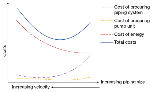 Figure 5.1. Key cost components for a pumping installation as related to pump size
Some costs increase with increasing pipe run size while other costs decrease. An optimum pipe run size, therefore, may be found based on minimizing costs throughout the life of the system (see Figure 5.1). For more information about improving pumping systems, see Optimizing Pumping Systems: A Guide for Improved Energy Efficiency, Reliability, & Productivity.
