

Part 1 of this article, which ran in the Pumps & Systems’ July 2020 issue, discussed various properties related to bolt strength, as well as some challenges often encountered in developing and maintaining a successful clamping load.
Part 2 will use the short form torque equation to evaluate the required bolt load necessary to develop a given gasket sealing stress and resist the design hydraulic pressure. This article will also review the challenges discussed in Part 1 and will enumerate the additional bolt load that might be used to account for each of these.
 Once the total bolt load is found, check the state of tensile stress in the A193 B7 bolts and compare the results to the bolt’s yield strength. With the additional state of stress evaluated, users can then judge whether the original choice of bolt material is sufficient to maintain the targeted gasket stress.
Case 1: Targeted Bolt Load for Operating Gasket Stress & Hydraulic Load
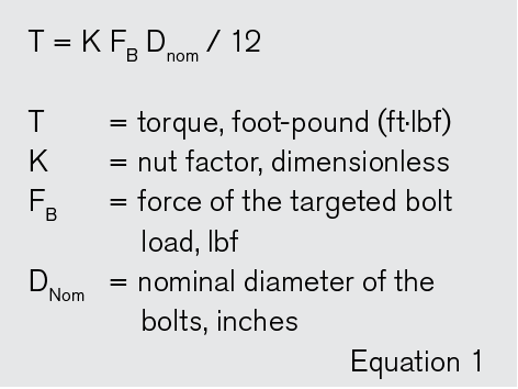
This example begins with a 6-inch, Class 150, A105 welding neck flange. There are eight 3/4-inch diameter stud bolts. The ASME B16.21 6-inch gasket has a contact outer and inner diameter of 8.50 inches and 6.62 inches, respectively. The design pressure and temperature are 200 pounds per square inch gauge (psig) at 400 F. The operating gasket stress is taken as 3,000 pounds per square inch (psi). Equation 1 provides the short form torque equation for a given bolt load and diameter.
The nut factor selected for the torque evaluation is 0.175. Please note, this value is provided as an example only. The best available value should always be used to account for the particular lubrication used (or lack thereof) and the condition of the bolt. The best results are obtained by actual testing.
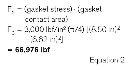
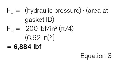
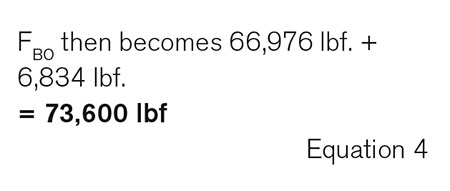
Now evaluate the initial bolt-up load (FBO) to retain a 3,000 psi gasket stress, after the hydraulic pressure has been applied. This is the sum of FG (bolt load for gasket stress) and FH (bolt load for hydraulic pressure).
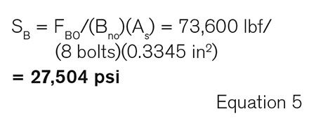
To evaluate the stress (SB) in a given bolt at this load, use the tensile stress area of the bolt, not the nominal area. The tensile stress area of a 3/4-inch 10 UNC stud bolt is 0.3345 in2. The tensile stress in a given bolt is evaluated in Equation 5.
Considering only the targeted gasket and hydraulic load , the bolt stress is well below its 70 F yield stress of 105,000 psi. Now evaluate the considerations given in Part 1.
Case 2: Temperature, FT
First, consider the decrease in bolt strength from 70 F to 400 F. From Image 2 in Part 1, there is a reduction in bolt strength of 5.7 percent. This reduces the stress on a given bolt by 0.057 x 27,504 psi = 1,568 psi.
The loss of bolt force, on a per bolt basis, is calculated by multiplying the loss in bolt stress times bolt true stress area (1,568 psi x 0.3345 in2 ) and is found to be ~525 lbf. Totaling the loss of eight bolts, the compensation becomes FT = (8)(525 lbf.) = ~4,200 lbf.
Case 3: Gasket Creep & Relaxation, FCR
For this hypothetical example, assume that testing verifies a creep relaxation value of 15 percent of its original value. Now multiply FBO by 15 percent and get the additional force required to compensate for the creep relaxation loss of the gasket. The compensating becomes FCR = 0.15 x 73,600 psi = 11,040 lbf.
Case 4: Cyclic Loading, FC
It is recommended that the gasket manufacturer be consulted for the best available values. For this example, presume a reduction in gasket stress of 5 percent. The increase on bolt load to compensate for the cyclic loading becomes FBO x 0.05 = 3,680 lbf.
Case 5: Equipment Misalignment, FMIS
Equipment misalignment is one of the more difficult compensations to make. There is no practical method to measure the load that misalignment introduces to the bolt-up condition. The ASME PCC-1, Appendix E provides useful guidance on limits of the various types of misalignments.
A best practice is to follow this guidance. However, to demonstrate the potential effect of misalignment, consider the case where the misalignment is presumed to raise the bolt-up load by 20 percent. The additional compensation of FMIS = FBO x 0.20 = 14,720 lbf is now added.
Case 6: Embedment Consideration
The value of bolt load lost to embedment, like so many conditions affecting bolt load, will have a range of applicable values and is never really known to a high degree of precision. A value as high as 10 percent is not uncommon. New bolts versus used bolts will have a higher amount of embedment. In this example, presume the bolts are in new condition. The additional compensation becomes FEM = FBO x 0.10 = 7,360 lbf.
Tally of Compensations
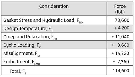
In Image 1, tally the load compensation for the five additional considerations with Case 1. With these, the full tensile stress in the bolt(s) can be evaluated and the bolting choice can be judged.
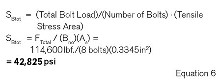 Including these considerations shows that the bolt-up load increases from 73,600 lbf to 114,600 lbf. This is approximately 56 percent higher than the initial targeted bolt load for a given value of gasket stress and hydraulic load alone. With these compensations added, evaluate the total state of tensile stress in the bolts. The final check is shown in Equation 6.
Recall that the yield strength of the bolting material from Part 1 is 105,000 psi. With this compensation, the percentage of yield strength at bolt-up is S%yld = (42,825 psi) x (100)/(105,000 psi) = 41 percent. This is well within an acceptable range of loading for these bolts. The choice of bolt is acceptable.
In Part 2, an example has been made of various types of loading compensation that can be used to ensure the initial bolt-up load is sufficient to overcome the challenges in maintaining a successful gasket stress. These values may be applicable to some conditions, but they are not intended to be used without technical discretion.
To be successful, this information is dependent on the specific components and conditions. Correctly applying them can improve site safety, mitigate fugitive emissions and reduce downtime.
We invite your suggestions for article topics as well as questions on sealing issues so we can better respond to the needs of the industry. Please direct your suggestions and questions to sealingsensequestions@fluidsealing.com.
