
First of Two Parts
02/25/2015
In this two-part series, how transient events in process equipment affect other system components will be discussed. Part 1 covers how deaerators (DAs) may be affected by generator trips and how these deaerator transients may also affect system pumps. A power plant includes a complex array of machinery, pipes, tanks, fuel, controls and auxiliary equipment. Figure 1 illustrates a simplified sketch of this system.
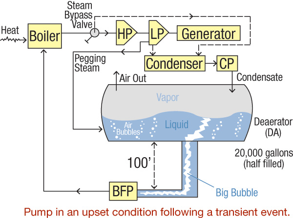 Figure 1. Simplified diagram of a power plant cycle (Graphics courtesy of the author)
The Steam Generation Process
Fuel heats the boiler to convert liquid to steam. High temperature and pressure feed the hot steam from the boiler to a turbine, which typically has several stages (high, intermediate and low pressures). The system includes additional components for better efficiency, control and reliability, but these are omitted to simplify the article. Steam turbine shaft rotation is transmitted to a generator shaft, and electric current is delivered to a net. Exhausted steam is dumped into a condenser where it is further cooled to complete its transformation back to cold water, which a condensate pump sends to a DA. The DA's size depends on the design and the plant's requirements, but a 20,000-gallon tank with roughly half its capacity filled is typical for a relatively small power plant.The DA's Function
The main purpose of a DA is to remove entrained air, which is accomplished by extracting auxiliary (pegging) steam from the low-pressure steam turbine. This steam heats the water and strips it of most of the air and keeps the fluid in the DA at saturation temperature. The deaerated water flows to the boiler feedwater pump's (BFP) inlet, which moves it to the boiler, and the cycle repeats.Process Transients
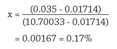
Problems that may interrupt this process include a sudden reduction or a complete loss of generator load (a load rejection condition). When the generator trips, steam is bypassed through the diverting valve around the steam turbine and is typically directed into the condenser. A less common method is to release the steam directly into a DA or to the atmosphere. During roughly the same time, fuel is diverted from the boiler, and the boiler begins to cool. Condensate pumps continue to operate to keep up with the cooling steam arriving at the condenser. Because the pegging steam has been diverted to the condenser, it no longer pressurizes the DA. The continuous arrival of the condensate into the DA cools the liquid. As a result, the temperature and pressure in the DA drop. The temperature falls as the condensate cools it, and the pressure decreases because of the loss of pressurizing pegging steam. A basic understanding of thermodynamics provides the foundation for what happens next. Steam tables and graphs contain information about pressure, temperature, specific volume, enthalpy (energy), entropy and quality of the water in its different states—liquid, vapor and mixed. Figure 2 depicts a temperature-specific volume (T-v) diagram, with tabulated data and examples.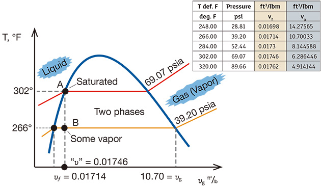 Figure 2. The T-v diagram shows the thermodynamics of the transient inside the DA.
(Source: Cameron Hydraulic Data Book, 19th Edition, 2002)
Figure 2. The T-v diagram shows the thermodynamics of the transient inside the DA.
(Source: Cameron Hydraulic Data Book, 19th Edition, 2002)
Conlusion
This article simplified these power plant processes, so additional factors affecting these types of transients and possible remediation actions must be considered. One important aspect not addressed in this article is the DA tank being only partially filled. The void above the liquid has significant effects. The specifics of DA design and operation, however, are not addressed here. For readers with a sharp eye who find this (and perhaps other) omission(s) significant, please feel free to share your thoughts and analysis. How do you handle transients? The best response will win a free admission to the next Pump School sessions. Part 2, in the April 2015 issue, will examine how a system that uses multiple pumps could be affected by a transient event. For a video accompaniment to this article, click here, and for other videos in this series, click here and view PVA #10. References- Cameron Hydraulic Data Book, 19th Edition, 2002
- Rovnak, J., Wotring, T., Marshall, J., Evaluation of NPSH During Hot Restarts of Fossil Plants with Deaerators, International Power Generating Conference, ASME, 91-JPGC-Pwr, 23, October 6-10, 1991
Read part 2 of this series here.
