

Like the flashy movie star in a Hollywood film, the pump impeller gets all of the media coverage, glitz and glamour. Everyone remembers who starred in the movie but, with few exceptions, no one remembers or ever knew the sidekick, the gaffer, the grip or the best boy. As an example, look up Tracey Walter, who appeared in 87 movies and 39 TV shows, and next search for John Higgins, who is one of the best gaffers in the industry. I guarantee you have seen at least one of his movies. Did you know Tracey or John prior to this column?
Without the support of the crew, the movie star is just another person on the street, and without the casing, the impeller is just a shiny piece of rotating metal. Further, like a great movie, the impeller and casing must be matched to each other or the results will be a disaster.
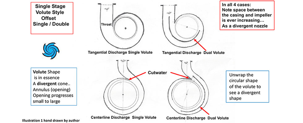
Casings—like people—come in all shapes and sizes and are designed for different and specific purposes. One casing design will have the centerline offset (noncongruent) from the impeller centerline to form an ever-increasing annulus (chamber) that is, in essence, a divergent nozzle similar to an Archimedean spiral. Or you can also imagine it as a large horn (think French horn or trumpet) that is wrapped in a circular shape.
The reason for the offset centerline is so the pump will be more efficient. The downside of the design is that the radial thrust will increase exponentially as operation departs from the best efficiency point (BEP). Other casing designs will have their centerline congruent with the impeller (concentric). While that pump is less efficient, the radial thrust will be much lower, and the reliability will be much higher even at operating points far from BEP.
Some casings have tangential discharge nozzles and others are orientated to the centerline. Tangential casings are easier to design and cast. They also offer less wear when handling solids and slurries. The centerline nozzle will be self-venting and, dependent on specific speed and good design, may be more efficient.
So far, I have only used the nomenclature casing, but there are other names used in the industry. Some are specific and some are more general—many are misused. Casings may have other descriptors such as tubular or elbow. Other common names may be volute, scroll, snail (snail shell) or diffuser. Under the umbrella of volute, you will see further descriptions such as single, double and sometimes triple. I have read about quad volutes utilized in nuclear primary coolant service but have yet to see one in service. There are also combined volutes, vortex volutes, low flow-high head volutes and self-priming volutes.
A casing with guide or stay vanes is typically known as a diffuser casing but you can also have vaneless diffusers. Normally the diffuser is cast as a separate piece from the casing. On high pressure multistage pumps, the casing may be referred to as the barrel. And what is a multistage pump other than numerous pumps placed in series conveniently incorporated into one casing?
What Is the Purpose of the Volute?
The typical volute consists of a spiral collector and a vaneless diffuser (throat). Look at a small (OH-1) ANSI B73.1 or ISO 5199 pump casing to visualize. Many people in the pump world will answer the question by stating that the volute is the device that converts the high velocity of the liquid (imparted by the impeller) to pressure energy (head), and they would be correct. Let me add that if the pump was not connected to piping (piping that exhibits some amount of friction resistance), the pump would develop flow but not develop pressure/head.
Maybe it is more important to know that, in real-world applications where discharge piping is connected to the pump, the volute works to keep the liquid velocity constant for the full 360 degrees around the circumference of the impeller (well at least near the BEP). The idea and the goal are that at BEP the pressure gradient surrounding the impeller will be uniform. By the way, the purpose of a diffusor is to simply convert the velocity to pressure, which is what happens in the volute/casing when the pump is operated away from BEP. That is, the volute acts like a volute near BEP but acts like a diffuser when you move far left or right on the curve.
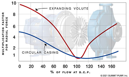
For pumps operating right or left of the BEP design point, the effect of the resultant radial force is the same on either side but the direction is opposite. For a single volute casing and a medium to low specific speed impeller, the resultant radial thrust for a pump operating to the left (near shutoff) would manifest at 240 degrees from the volute cutwater (aka flow divider, splitter or tongue). For the same pump that is operating at the far right of the curve near or approaching runout, the resultant radial force would manifest at 60 degrees from the cutwater.
Note there are forces with radial components acting all the way around the impeller, but when you work the geometry (vector analysis), it is the resultant of all the forces we are concerned about. By using a concentric casing where the centerline of the impeller and the casing are congruent, the magnitude of the aforementioned radial forces would be significantly less.
You can also state that the purpose of the casing/volute is to both direct and contain the liquid flow. It is a connection point for the suction and discharge piping. A joke I make with pipefitters and millwrights is that the pump casing is an anchor point for the piping. Note that this is a joke, as a pump would be the most expensive pipe anchor point you ever purchased. You should never support the weight of the pipe and contents onto the casing. Not to be confused with nozzle loading allowable forces and moments. Perhaps a subject for a future column?
Who Is Doing the Work?
Regarding the division of labor issue, a common axiom is that the impeller does all of the real work and the casing works solely to minimize the losses. For today’s purposes let’s assume that is 100% true. It is, however, wrong to conclude that the two components operate independently of each other.
Subsequently, it may be a better perspective to revise the current thinking and see that the casing can make all the difference in how efficiently the impeller does its work. A bad casing design can make an impeller inefficient. In the early days of centrifugal pumps (1850s), Henry Bessemer designed a pump casing that yielded 16% efficiency; yet, during the same era with a similar impeller, John Appold designed a casing that was 68% efficient.
Casing Design (Conservation of Angular Momentum)
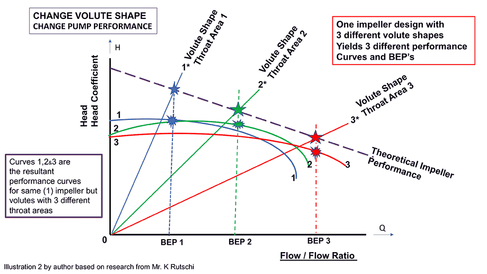
A given casing design has a theoretical head to flow rate relationship that may look a little like a theoretical pump curve except the head rises from zero with increased flow rates. The impeller has a similar flow to head relationship curve but the head is maximum at no flow and decreases with increased flow rates.
The pump BEP is normally where these two “curves” intersect (in theory, these look more like straight lines than curves). Designing the impeller and casing to match each other will result in the most efficient and reliable pump. Of course, the volute inlet area has to be large enough to allow the flow required by the pump impeller. The important part is that the liquid velocity is evenly distributed around the periphery of the impeller eye (think equal loading).
Once the liquid has left the impeller and is exiting the pump, the casing design criteria becomes much more critical. Like most pumps, the casing design point is based on the BEP flow rate with diminishing concern for flows that depart from BEP. The alternative is to design a pump for small increments of flow change, which translates into hundreds of different
sizes for the same model. The business and commercial world does not support that position.
To make the impeller and volute work well together, we need to look at the ratio of the impeller outlet area and compare that to the area of the volute throat. Additionally, the impeller outlet velocity must be compatible to the mean velocity in the volute throat.
Keep in mind that the velocity of the liquid leaving the impeller is swirling—aka whirl velocity (angular momentum). The flow exits the impeller with a spiral path; the circumferential components of the velocity are related to the head developed, while the meridional component is related to the flow rate. If all the pictures/illustrations you see of pump cross-sectionals are two-dimensional, you may miss this point.
Previously you may have thought the pump’s specific speed was solely a function of the ratio of the impeller’s width to the diameter and, to a lesser degree, the angle change for the liquid as it enters and exits the impeller, but there is more. These ratios of area and velocity indicate the pump’s specific speed is also a function of the ratio between the square root of the volute throat area and the impeller diameter.
So, specific speed isn’t purely a function of the impeller; it is also partially a function of the casing design. At low specific speeds (400), the ratio is at its highest, but as you increase (move up) the specific speed scale to around 2,800 the ratio diminishes.
For engineers and technicians that want more detail, foundation equations and derivation on this subject, please see the references.
Cutwater/Flow Divider/Splitter
The placement of the cutwater, length, thickness and angle in relation to flow and the profile of the leading edge will all have an important role in the casing efficiency and overall pump performance. I will discuss this topic in a future column.
Hopefully you have a higher appreciation and better understanding for the role of the casing (volute) after reading this column. Every time you leave the casing in the piping while you are working on the “back pull out,” not inspecting for or measuring wear in the casing or simply leaving the casing on the shop floor until “we get the impeller fixed,” know that even the best impeller really can’t do a good job without help from the casing. Well, unless the impeller is maybe Clint Eastwood.
References
Centrifugal Pumps, Johann Friedrich Gülich
Centrifugal and Axial Flow Pumps, Alexey Joakim Stepanoff
Centrifugal Pumps Design and Application, Val S. Lobanoff and Robert R. Ross
