
This four-part series explains the reasons behind repeat pump failures and uses a real-world field example involving boiler feedwater pumps.
08/21/2014
Part 1 of this article series was published in the July 2014 issue of Pumps & Systems.
Despite their simplicity, centrifugal pumps often experience repeat failures that even seasoned maintenance and reliability professionals have trouble preventing. This four-part series explains the reasons behind repeat pump failures and uses a real-world field example involving boiler feedwater pumps. Deviations from best practices or oversights can range from seemingly insignificant to stunningly elusive. These can combine and often cause costly failures.
Operating Different Pumps in Parallel
The negative experience of a metal producing facility best demonstrates the consequences of operating pumps beyond their appropriate flow ranges. This example serves as a reminder of the merits of conducting in-depth reliability reviews before buying process pumps. This case history extends to the remaining parts of this series. The operating data of the plant’s installed instrumentation is shown in Figure 1. The flow rate into the destination tank averages 2,500 gallons per minute (gpm) to maintain the tank level. This system currently operates for 8,000 hours per year to meet the plant’s production needs. The system has operated in this way since being commissioned five years ago.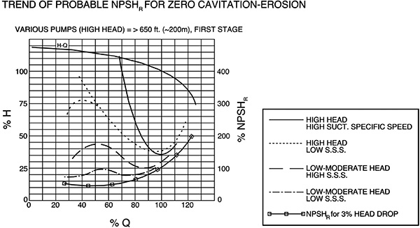 Figure 1. Pump manufacturers usually plot only the net positive suction head required (NPSHR) trend associated with the lowermost curve. At that point, a head drop or pressure fluctuation of 3 percent exists at BEP flow.1
Low-Flow Range
At least two of the pumps had flat H/Q curves, similar to the curve in Figure 2. Running in the low-flow range forced one or both pumps into the flat portion of their respective performance curves. When operating in the flat range, even a small change in head (a small change in ∆p) results in large differences in throughput. Controlling and equalizing load sharing would be difficult.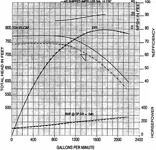 Figure 2. A typical head-versus-flow performance curve
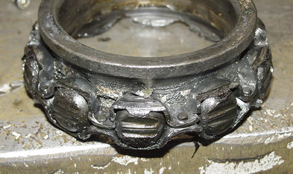 Image 1. This riveted cage bearing failed because of axial (rotor thrust) overload. (Article images and graphics courtesy of the author.)
References
- Taylor, Irving, “The Most Persistent Pump-Application Problems for Petroleum and Power Engineers,” ASME Publication 77-Pet-5 (Presented at Energy Technology Conference and Exhibit, Houston, Texas, September 18 – 22, 1977).
- Bloch, Heinz P., Pump Wisdom: Problem Solving for Operators and Specialists, John Wiley & Sons, Hoboken, N.J., 2011.
- Bloch, Heinz P. and Alan R. Budris, Pump User’s Handbook, 4th Edition, Fairmont Press, Lilburn, Ga., 2013.
- ANSI/HI9.6.3-1997, “Allowable Operating Region,” Hydraulic Institute, Parsippany, N.J.
- SKF USA, Inc., Publication 100 – 955, “Bearings in Centrifugal Pumps,” Version 4, p. 20, Kulpsville, Pa., 2008.
- Bloch, Heinz P., Practical Lubrication for Industrial Facilities, 2nd Edition, Fairmont Press, p. 179, 2009; “Mechanical Seals in Medium-Pressure Steam Turbines,” presented at the ASLE 40th Annual Meeting in Las Vegas, Nev., May 1985 (later reprinted in Lubrication Engineering, November 1985).
