

Managing fluid flow in different industrial applications requires the use of multiple valves which start, stop or redirect the flow of fluids. Most of these valves are two-way, meaning they have an inlet and outlet port.
However, some flow applications require a third port, providing two inlet ports and a single outlet or two outlets and one inlet port. This implies that these valves can perform the same functions as two-way valves and exhibit better performance characteristics.
Three-way valves offer a cost-effective means to control fluid flow in different applications by minimizing or eliminating multiple two-way valves for certain operations. For instance, three-way valves can mix fluids with varying physical and chemical properties or divert the flow direction depending on the configuration of ports. Several types of three-way valves exist in the market to meet flow control needs for different industrial applications. These include three-way ball valves, three-way solenoid valves, three-way butterfly valves and multipath plug valves. In this article, the focus is on three-way ball valves. These valves contain three ports identified as A, B and AB.
Three-way valves are popular in industrial boilers, chemical mixing pipelines, steam collection and distribution systems, air conditioning devices and complex piping systems containing primary and secondary loops. These valves are available in two internal configurations, which affect their performance in the mentioned applications.
Types of Three-Way Valves
There are two broad categories of three-way valves, namely L-port and T-port. The L and T nomenclature represents the fluid flow path through the three ports, depending on the configuration of ports and the connection to adjacent pipelines.
L-Port valves
L-port valves are also called diverter or L-pattern valves. The L-pattern describes the fluid flow path as it travels from the inlet to the outlets. Usually, L-port valves have two outlet ports and a single inlet port.
The ports are identified as A, B and AB. Therefore, when port A is used as an inlet, ports B and AB are outlets. If port B is the primary inlet, ports A and AB become the outlets. In other configurations, port AB is the inlet port, while ports A and B act as the outlet ports.
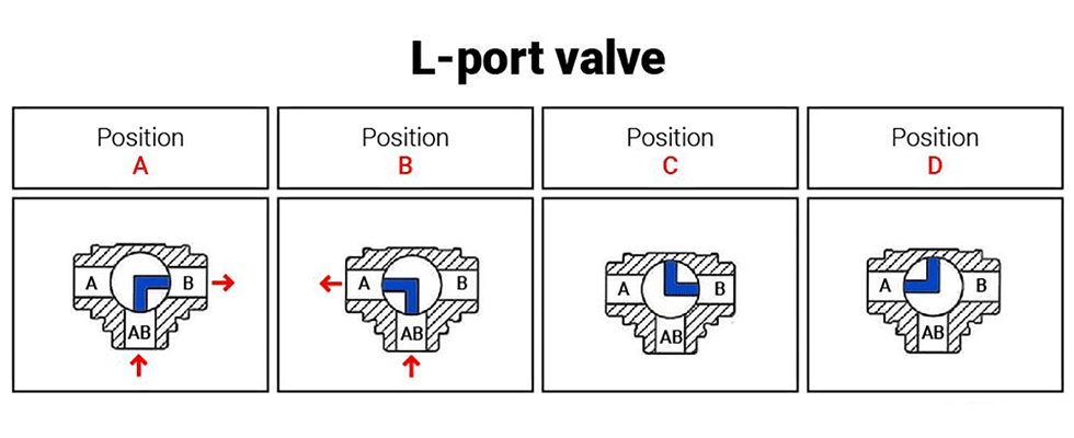
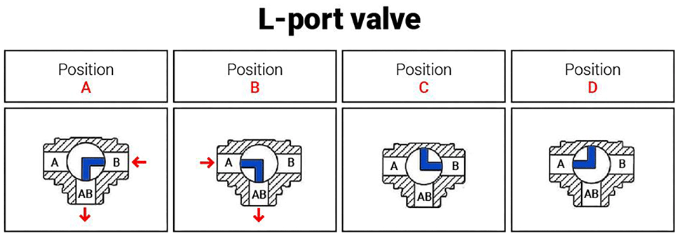
To illustrate how L-ports operate, consider a three-way ball valve with port AB as its inlet. Assume the fluid flows from the inlet port and travels in the right direction towards outlet port B, as illustrated below (Position A). The three-way valve contains a lever or actuator that moves 90 degrees to alternate the direction of fluid flow. When the lever travels 90 degrees clockwise, the ball blocks fluid flow through port B and redirects it towards the left–port A, which becomes the new outlet.
Another quarter turn moves the valves 180 degrees from their original position. At this point, the ball blocks the fluid flow through both outlet ports, and there is a total shutoff to fluid flow. Certain L-port valves can turn 360 degrees and have
two shutoff positions. L-ports can be installed in horizontal and vertical configurations. Port AB remains in an open position if the L-port valve is installed in a vertical pipe configuration.
T-Port valves
T-port valves are vital for converging (mixing) fluids from two sources and delivering them through a common outlet. The valves are essential for splitting fluids from one source in two directions. Therefore, these valves can have two inlets and a single outlet port or one inlet and two outlets. When using T-ports for fluid control in industrial processes, all the ports are in an open position at once. It implies that the valves can achieve the uninterrupted straight-through flow of service fluids. Like the L-port, T-port valves can fit in vertically and horizontally configured pipelines.
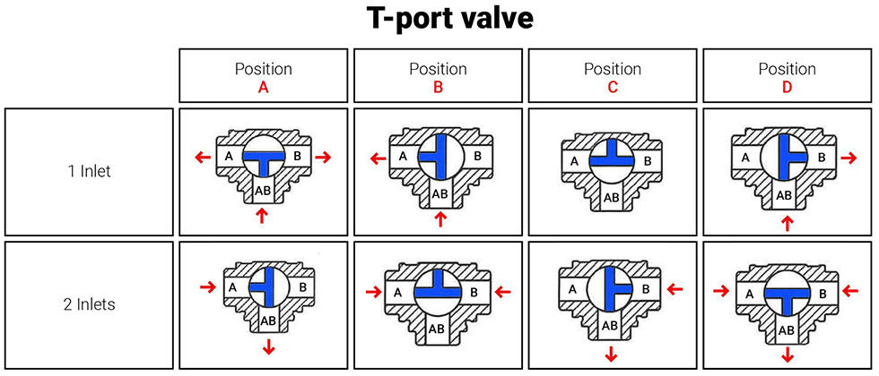
Actuating T-port valves 90 degrees causes them to depict similar performance characteristics as L-port, three-way valves. Fluid will flow from the common inlet and travel through one outlet port alone. Actuating the valve 180 degrees is inconsequential to fluid flow. One shortcoming of T-port valves is their lack of bubble-tight shutoff. These valves are unsuitable for pipelines demanding strict control of leakages and fugitive emissions. T-port valves are fitted with lock handles that control the quarter turn transitions of the flow control mechanisms. This feature facilitates better volumetric control when mixing or diverting service fluids.
Practical Applications of Three-Way Valves
T-port valves are mostly used for mixing services in industrial applications. The valves are connected to pipelines transporting different fluid compositions. As the fluids from the diverse sources merge at the valve, they mix in controlled proportions before moving to subsequent pipe sections or processes. T-port valves usually provide constant flow control, assisting engineers in mixing and sampling fluids at different pipe sections.
Diverting fluid flow is possible using L-port and T-port valves. L-port valves provide a fluid diversion to one direction at a particular time. However, T-port valves can divert fluids to two destinations at once. T-port valves can also allow for straight-through flow (from inlet port A to outlet port B), which could be diverted 90 degrees to the second outlet port AB. It is a common set up in T-port valves used in diverting applications, as this cannot be accomplished with an L-port arrangement. L-port valves can divert fluid between two storage tanks. Once one tank fills up, the valve (if automated) changes its position and directs incoming fluid into the empty tank. Depending on the configuration, T-port valves can also act like L-port valves to divert fluid flow between storage tanks.
Three-way valves can be manually operated or automated using electric, pneumatic or hydraulic actuators. The type of actuator used depends on the desired level of valve automation, level of responsiveness and the actuation forces required.
Pneumatic actuators are preferable for their cost-effectiveness and ability to sustain multiple valve cycles. Hydraulic actuators can provide better actuation torque but are more costly than pneumatic actuators. Some three-way valves are actuated using electrical actuators, which offer better precision but have lower duty cycles than pneumatic actuators. Three-way valves can provide flexible flow control in different applications. The multiple ports allow process engineers to customize industrial processes using fewer valves.
