

Vibrating excessively, squealing noisily, giving off higher than normal heat, pressure readings off the curve and leaking process fluids are all signs that a pump failure is imminent. To avoid more damage to the pump and downstream equipment, as well as costly repair downtime, it is imperative to get to the root cause of the pump issue and restore it to peak performance quickly.
Bearings, couplings and seals are the most common pump components to fail. Experience has shown that overlooking these items will not only cost in maintenance dollars but also in resources and downtime that will increase operating costs. Here is how to identify those parts failures, ferret out the root causes and prevent them from happening again.
1. Bearings: How They Fail
Many red flags may be indicators of bearing trouble brewing: increased vibration readings, noisier than usual operation and raised temperature around the bearing housing are all common warnings. Pay attention to these little signs. Do not ignore even minor rattling; by the time loud squealing is heard, the bearings are usually shot and the pump is about to lock up.
While bearings are typically lubricated at the factory, they will require an individualized lubrication schedule depending on the pump’s application and operating schedule. (One exception to this is sealed bearings.) Failing to keep bearings properly lubricated can lead to overheating and early failure.
An additional threat to proper bearing operation is lubricant contaminant. Grit and other contaminants can damage the bearing surface, causing inconsistent operation and shortening bearing life. A less common threat to bearings is misalignment and vibration, which can cause spalling and damage to the bearing surface over time.
How to prevent failure
Establish a regular lubrication schedule and document lubrication in a maintenance log. Avoid the common lubrication missteps outlined below.
- The number one lubrication mistake made in the field is adding grease while the pump is running. If the pump is greased while running, the grease will not reach the rolling elements and the bearings will run dry. Always shut down the pump before adding grease to the bearings.
- Never mix grease types. Different grease thickeners can be incompatible and cause starvation or hardening.
- Do not overgrease the bearings. Overlubrication can be just as damaging as underlubrication. Overgreasing can cause severe heat buildup and premature bearing failure. (Note that sealed bearings do not require additional greasing; if grease is added to sealed-type bearings, this could force the seal out of position.)
- Periodically inspect the lubricant. If it appears to be contaminated, have it analyzed to determine what type of contaminants are infiltrating the bearing housing. Once the type of contamination has been determined, take corrective action to prevent recurrence.
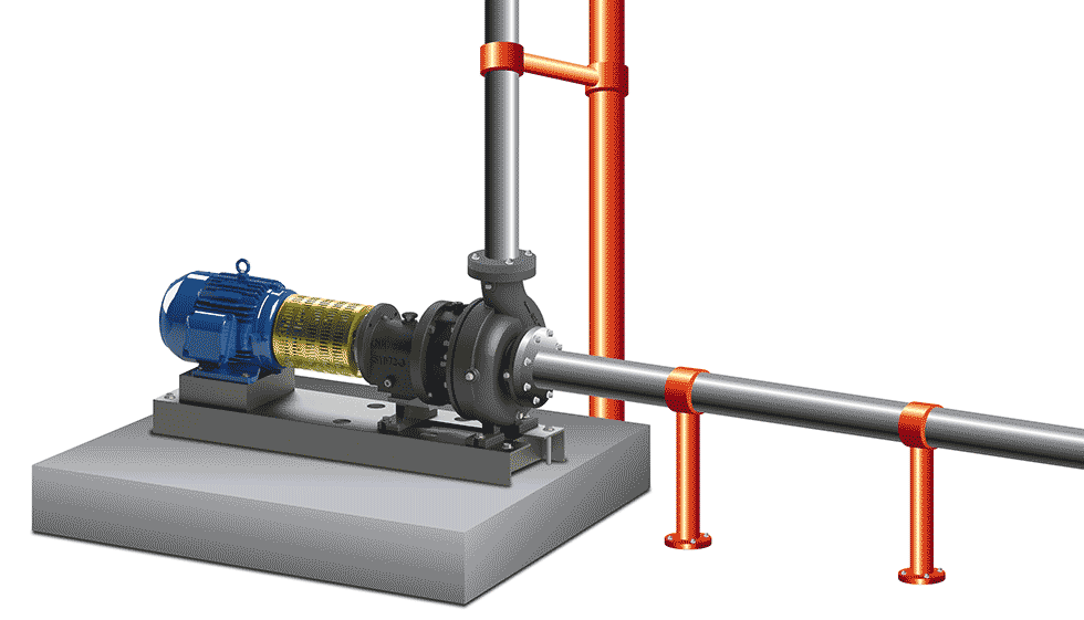
- Good system design and solid installation should prevent the excessive vibration that can lead to bearing spalling or pitting. Pumps should be mounted securely on a level base, with extreme care taken to support intake piping to avoid any strain on the pump. A pipe hanger installed on the discharge pipe should support all weight, not the pump or the casing. See Image 1 for proper installation and support. Regularly monitor equipment for changes in vibration and temperature to identify changing conditions.
2. Couplings: How They Fail
Couplings fail when the pump shaft and motor shaft are out of alignment. They may be out of alignment from the start due to improper installation or become that way over time due to system vibration. One way to visually identify a failing coupling is to look for black debris under the coupling area of the pump. This is from the coupling insert that is placed between the coupling flanges. On a misaligned coupling, the faces of the flanges rubbing together will grind down the insert over time, producing a pile of shavings.
The other key indicator of misaligned couplings is vibration. Any vibration above what is normally observed during the regular operation of the pump should be investigated.
How to prevent failure
Coupling alignment should be checked whenever trouble is suspected—due to the aforementioned shavings or vibration—as well as part of a routine maintenance schedule. Any time repairs are made to the pump, proper alignment should be verified both prior to startup and after the pump is at operating temperature (called “hot alignment”).
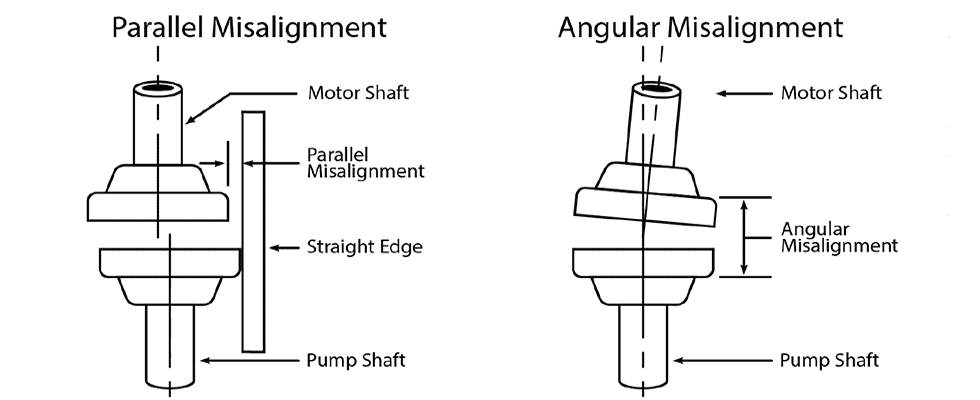
The parallel coupling alignment should be checked first by placing a straightedge across the two coupling flanges and measuring the maximum offset at various points around the periphery of the coupling. If the maximum offset exceeds what is specified by the coupling manufacturer, the coupling should be realigned.
Once satisfied with the parallel alignment, the angular alignment of the coupling should then be checked with a micrometer or caliper. Measure from the outside of one flange to the outside of the other at intervals around the periphery of the coupling. If the difference between the maximum and the minimum exceeds the tolerance specified by the coupling manufacturer, the coupling should be realigned. If correction is necessary, the parallel alignment should be rechecked. See Image 2 for proper coupling alignment techniques.
3. Mechanical Seals: How They Fail
Mechanical seal failures are usually pretty easy to spot—a slow drip or sometimes steady stream of process fluid originating from the seal gland is a dead giveaway. Seals account for most rotating equipment failures during the life of the equipment but are seldom the root cause of failure.
Wrong seal material selection for the process is a common mistake. Poor selection can lead to the seal’s O-rings swelling or cracking or corrosion of the seal’s face. While most people know to choose a seal based on the process fluid—e.g., a more robust seal is needed for corrosive fluid—many fail to take into consideration operating conditions. A fluid like water would normally be considered inert. However, add extreme temperature and there could be flashing and damage at the seal face.
Another temperature consideration that can impact the seal, even if the seal material has been properly selected, also has to do with operating conditions. Taking a stopped pump from ambient temperatures up to immediately running an extreme high temperature or supercooled fluid can thermally shock the seal and cause cracking.
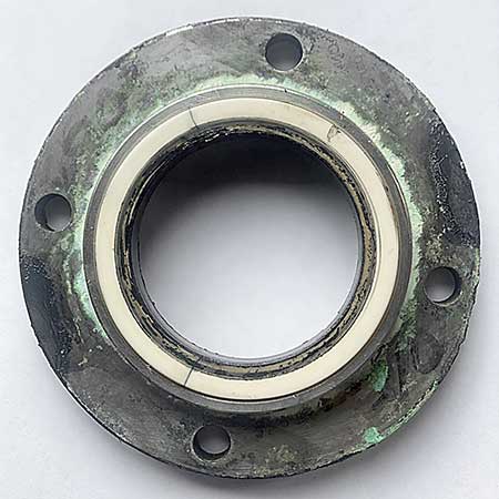
Pumps that move more viscous fluids such as paint can see buildup along the faces and edges of the seal. Over time, this can gum up the seal and cause failure. See Image 3 for an example of a seal that failed due to paint buildup.
Beyond these specific seal selection and application issues, the major cause of seal failure is dry running of the seal, which can cause thermal shock or burn up the seal’s elastomers. Any number of systemic problems can result in dry running. A low level of fluid from the source, blockages to the suction side of the pump, or running with closed discharge (dead heading) can all cause temperature to spike and lead to seal failure.
How to prevent failure
The first step in avoiding mechanical seal failure is to select the proper seal for both the process fluid and operating conditions. Review the application in detail with the application sales engineer instead of defaulting to selection by fluid type.
If extreme temperatures are involved, consider changes to startup procedures to avoid thermal shock to the seal. Gradually introduce the process fluid into the pump to bring all components up to full temperature more slowly. The addition of external heating or cooling elements is another possible solution.
For applications prone to process buildup on the seal, an external seal flush system can be added to keep those particles from sticking to the seal. If an external flush system is present on a pump, it should be maintained in good working order and checked if seal buildup and failure occur.
Once the proper seal material is selected for the application, focus should shift to the suction side of the equipment to prevent dry running. If fluid at the source regularly runs low, a level control switch should be installed to prevent low supply levels. If a discharge flow or pressure drop is observed, that is an indication the intake should be checked for blockages. Except for short periods for pump performance testing, a pump should never be run with a closed discharge—signage and lookout procedures can prevent this from happening.
A solution to troubleshooting seal problems is to retrofit the process with a sealless pump. These vertical-enclosed column designs reduce leakage across the throttle bushing, collect any incidental leakage within the pump column and discharge it back to the suction or supply tank. Vertical sealless pumps are suited to a wide variety of challenging applications—even those with high solids or with high temperature fluids. Retrofitting a horizontal pump installation with an enclosed column vertical pump can typically be accomplished with minimal piping changes and the addition of supports for external mount configurations.
Documentation
Conventional wisdom asserts that those who do not learn from history are doomed to repeat it—this holds true when it comes to pump maintenance and repair. Documenting repairs can help identify future problem pumps and aid in diagnosing future pump failures. This important final step is often overlooked once a pump is up and running again.
There are several key elements to note. The more details that are documented, the easier it will be to pinpoint those outlier factors. For starters, maintenance notes should include any unusual operating conditions around the timing of the repair issue (e.g., a period of shutdown for a holiday, exceptionally high temperatures, etc.). Note the pump’s location in the process and the reason the pump was identified for repair (stoppage, performance, leakage, noise, amps, etc.).
Repair notes should also include the diagnosis and steps taken to repair the pump. When identified as a problem pump, it can be flagged for closer inspection of the installation, piping, operation and repair procedures. This closer inspection should result in identifying the root cause of the failures.
Using historical data to eliminate recurring problems will extend pump life and prevent process downtime.
