
Last month’s column (Pumps & Systems, October 2014) described the collection of data when assessing a system with no control. In this column, the plant operating data will be used to determine a baseline of how much energy is used for the process. Personnel and outside experts can then look for ways to improve the system and minimize costs. Assessments are based on the idea that a system was originally designed to meet a specific set of requirements, but during the design process, several unknowns were incorporated. Once a plant is operating, the unknown design factors become known, and the system can be improved. This column explains how to perform the baseline calculations and develop the energy cost balance sheet to determine how energy is used by the system.
Energy Cost Balance Sheet
During the system walk-down, the assessment team discovered that the operators continually operate Pump BTP-01. Once the batch tank fills, a bypass to Supply Tank BTS-01 automatically opens when all fill valves close to ensure that minimum flow is maintained through Pump BPT-01. In previous columns, the energy cost balance sheet was discussed as a way to obtain the actual cost of operation for each item in the system. The energy cost balance sheet calculates the energy consumed by the pump to operate the system along with the energy consumed by the process and controls to make the product or provide the service. In this system, the system control consists of running the pump in the bypass mode when the tanks are not being filled.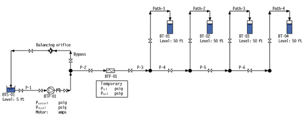 Figure 1. The batch tank fill piping system fills the 60,000-gallon batch tanks before starting a three-hour batch process. (Graphics courtesy of the author)
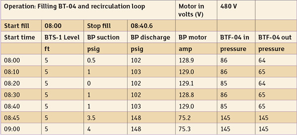 Table 1. The operating data collected during the assessment when filling BT-04 and the minimum flow recirculation (updated—see Author’s Note)
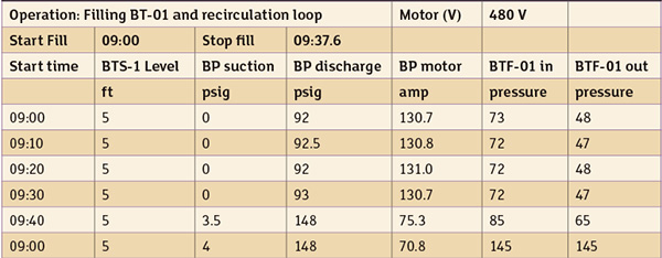 Table 2. The operating data collected during the assessment when filling BT-01 and the minimum flow recirculation (updated—see Author’s Note)
Pumping Elements
The pumping power is calculated using Equation 1. Using the assessment data for filling Batch Tank 4 and with the manufacturer’s supplied data, Equation 1 can be used to calculate the power consumed by the batch pump in each operating mode. Where:
Ppump = Pump power in
kilowatts (kW)
Q = flow rate in gallons per minute (gpm)
H = pump head in feet (ft) of fluid
ρ = fluid density in pounds per cubic foot (lb/ft3)
np = pump efficiency
nm = motor efficiency
nvsd = variable speed drive (VSD) efficiency (1 if no VSD is installed)
Because an electric motor drives the pump, the input power to the motor can be calculated using Equation 2 and the data collected from the assessment.
Where:
Ppump = Pump power in
kilowatts (kW)
Q = flow rate in gallons per minute (gpm)
H = pump head in feet (ft) of fluid
ρ = fluid density in pounds per cubic foot (lb/ft3)
np = pump efficiency
nm = motor efficiency
nvsd = variable speed drive (VSD) efficiency (1 if no VSD is installed)
Because an electric motor drives the pump, the input power to the motor can be calculated using Equation 2 and the data collected from the assessment.
 Where:
P3θmotor = motor power (kW)
V = voltage volts
I = current amps
Pf = motor power factor
These are two independent methods for calculating the power used by the motor and pump. If the calculated power of the motor and pump are identical, the results have been cross validated.
Where:
P3θmotor = motor power (kW)
V = voltage volts
I = current amps
Pf = motor power factor
These are two independent methods for calculating the power used by the motor and pump. If the calculated power of the motor and pump are identical, the results have been cross validated.
Calculating Pump & Motor Power Consumption
Using the operating data collected during the system assessment for filling Batch Tank 4 (Table 1) and Equation 1, one can determine the power requirement for the batch pump (see Equation 3).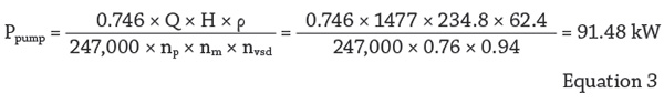 The pump flow rate (Q) can be determined using the time required to fill Batch Tank 4. Because filling the 60,000-gallon batch tank took 40 minutes and 36 seconds (40.6 minutes), the calculated flow rate through the pump is 1,477 gpm.
The pump head is calculated by measuring the differential pressure across the batch transfer pump. The average differential pressure using the supplied data is 101.6 pounds per square inch differential (psid). With a fluid density of 62.4 lb/ft3, the total pump head is 234.8 ft.
The pump and motor efficiency can also be determined. The pump efficiency is taken from the manufacturer’s pump curve. Given the pump’s impeller diameter (17.5 inches) and calculated flow rate (1,477 gpm) the pump’s efficiency from the pump curve is 76 percent. The motor efficiency of 94 percent was found on the motor nameplate.
The power supplied to the electric motor can be calculated using the motor voltage, current, efficiency and power factor (see Equation 2).
The power factor listed on the motor nameplate is 0.85. Based on the current and voltage readings from Table 1 for filling Batch Tank 4, the motor power consumption is calculated using Equation 4.
The similarity between the values calculated for electrical power consumed using pump data (Equation 1) and the electrical power consumed using motor data (Equation 2) shows the close correlation between the two methods.
Using the operating data along with the pump and motor energy calculations, a table that shows the power consumed by the pump during the two fill modes and two bypass modes can be developed (see Table 3).
The data show that filling Batch Tank 4 requires 40.6 minutes. This is because Tank 4 is the farthest from the pump, causing a higher head loss in the connecting pipeline. This results in a lower flow rate through the pump. When not actively filling the tanks, the bypass is open and none of the energy consumed is used to fill the tank. When Batch Tank 4 is full, the pump operates for 19.6 minutes in bypass mode. Filling Batch Tank 1 requires 37.6 minutes. This results in 22.4 minutes in bypass mode during the hourlong fill cycle.
The pump flow rate (Q) can be determined using the time required to fill Batch Tank 4. Because filling the 60,000-gallon batch tank took 40 minutes and 36 seconds (40.6 minutes), the calculated flow rate through the pump is 1,477 gpm.
The pump head is calculated by measuring the differential pressure across the batch transfer pump. The average differential pressure using the supplied data is 101.6 pounds per square inch differential (psid). With a fluid density of 62.4 lb/ft3, the total pump head is 234.8 ft.
The pump and motor efficiency can also be determined. The pump efficiency is taken from the manufacturer’s pump curve. Given the pump’s impeller diameter (17.5 inches) and calculated flow rate (1,477 gpm) the pump’s efficiency from the pump curve is 76 percent. The motor efficiency of 94 percent was found on the motor nameplate.
The power supplied to the electric motor can be calculated using the motor voltage, current, efficiency and power factor (see Equation 2).
The power factor listed on the motor nameplate is 0.85. Based on the current and voltage readings from Table 1 for filling Batch Tank 4, the motor power consumption is calculated using Equation 4.
The similarity between the values calculated for electrical power consumed using pump data (Equation 1) and the electrical power consumed using motor data (Equation 2) shows the close correlation between the two methods.
Using the operating data along with the pump and motor energy calculations, a table that shows the power consumed by the pump during the two fill modes and two bypass modes can be developed (see Table 3).
The data show that filling Batch Tank 4 requires 40.6 minutes. This is because Tank 4 is the farthest from the pump, causing a higher head loss in the connecting pipeline. This results in a lower flow rate through the pump. When not actively filling the tanks, the bypass is open and none of the energy consumed is used to fill the tank. When Batch Tank 4 is full, the pump operates for 19.6 minutes in bypass mode. Filling Batch Tank 1 requires 37.6 minutes. This results in 22.4 minutes in bypass mode during the hourlong fill cycle.
