

Operating at low flow places the machine under a great amount of duress. It is always wise to have a mental picture of what is happening within the passages of the machine to understand why this is the case.
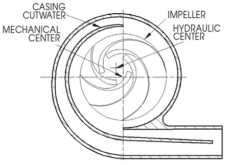 IMAGE 1: Hydraulic cam causing high 1x vibration (Images courtesy of Hydro Inc.)
Vibration 1x
The days have long passed where pump vibrations were viewed as a matter of mechanical balance. Now, we recognize that even if the pump had perfect mechanical balance, it would still exhibit vibrations.
The intensity of this remnant vibration turns out to be flow related with its minimum level being at or around best efficiency point (BEP).
Vibration at “one times” shaft rotational frequency is often ascribed to mechanical balance. However, this can also be caused by the impeller if it is machined eccentrically to its hydraulic center. The impeller behaves like a hydraulic cam while in the pump, even though it may be in near-perfect mechanical balance in air.
No amount of mechanical balance can reduce this cam effect as each blade passage is a different length and holds a different weight of liquid. Performing a mechanical balance in air cannot solve this issue.
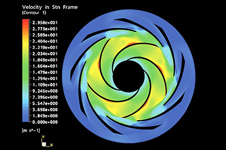 IMAGE 2: Velocity experienced by diffuser
Hydraulically Generated Vibration—Vane Pass
From a hydraulic design standpoint, vibrations at vane pass frequency are always present due to the way impellers generate head. This vibration is inevitable, and the only pump that does not have vane pass vibration is one that is not running.
Each vane had a pressure differential between the pressure (top) and suction side (under) of the vane. This pressure differential results in a velocity difference over both surfaces of the vane that also fluctuates with its position relative to
the diffuser.
This difference spreads into the diffuser and anything connected to it will experience a fluctuating pressure field once per impeller blade pitch.
At partial capacity, this flow picture greatly deteriorates. Each passage is filled with slow moving fluid. Operated in this condition, it is easy to see how vibration and heat can become a problem for pump reliability.'
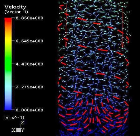 IMAGE 3: Spiraling inlet backflow in suction piping
Vibration Caused by Inlet Backflow Recirculation
The phenomenon is always present within a pump operating at low capacity and always contributes to the vibration level.
High-energy liquid is expelled from the impeller eye. Each impeller blade generates an individual stream, and these velocity streams, impacting on features in the suction nozzles and suction pipework, contribute to the vane pass frequency vibration.
From these images, it is easy to understand why the disturbed flow regimen within a pump can cause so many reliability issues. In all of these situations, the flow is violently disturbed when it should be smooth and follow the passage shape. Living with a machine at partial capacity means an inevitable adverse effect on pump reliability.
