

There is a lot of buzz around optimal pump selection. Much of the discussion encompasses pump system design optimization. What is lacking in these discussions is a consensus about what optimization means, how it is achieved and what the outcomes are for an optimized pump. People use “optimized” to refer to any of the following pump qualities:
- the pump with the lowest initial cost
- the pump that consumes the least amount of energy
- the pump with the lowest lifetime maintenance
- the pump that lasts the longest
Each is a worthy goal in specifying a pump; the more that can be achieved, the more optimized the pump. However, these goals may not align in the real world.
Alignment is more likely to occur in clean fluid pump applications. In applications involving fluids other than water or that contain solids or air, this alignment is more difficult to achieve.
Before pump selection can be optimized, the design goals and processes of the entire system need to be understood. In the pump world, there are few bad pump designs. However, it is quite common for a user to place blame on a pump following a failure.
Pump and mechanical seal failures are rarely the result of a bad pump or seal design. Rather, the vast majority of premature pump failures are the result of:
- improper pump selection for a given system
- improper operation of the system (outside the original intent for the system)
- improper installation
This article will focus on the selection and operation pieces. While proper installation is critically important to successful pump operation, the scope of this article must necessarily be limited. Always follow the manufacturer’s installation recommendations.
Defining Optimal Pump Operation
To understand how to achieve optimal pump selection, what optimal pump operation looks like must first be understood.
Pump manufacturers, through performance testing, determine the efficiency for each model pump. This point is called the best efficiency point (BEP). BEP should be stated on all centrifugal pump curves. At the BEP, the least amount of fluid is bypassed back to the low-pressure (or suction) side. The pump runs the smoothest at this point, the flow is the cleanest moving through the pump, and there is minimal radial (or side) loading on the pump bearings.
During normal operation, a good rule of thumb is that a centrifugal pump should always be operated between 50% and 120% of the BEP. The reason for this range is based on the physics of the design. Operation in this zone ensures the highest efficiencies and the most reliable operation, with the lowest bearing loads, turbulence and vibration.
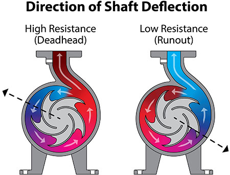
If flow is reduced by restrictions in the system, an area of relative low pressure develops past the cutwater in the casing. This results in a force that deflects the impeller and shaft toward that area as the pump spins (approximately 300 degrees from top dead center).
Conversely, if too little restriction is created in the system, a low-pressure zone is produced before the cutwater, causing the shaft and impeller to be deflected toward that low-pressure zone (approximately 120 degrees from top dead center).
Neither of these conditions is good for pump and mechanical seal health. Image 1 is the resultant pressure differential inside a casing in these conditions.
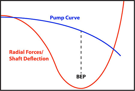
This pressure differential causes increased shaft deflection, vibration and bearing load. Image 2 illustrates the amount of this potentially damaging radial load and shaft deflection relative to a performance curve, with the lowest radial load near the pump’s BEP.
It would seem on the surface that selecting a pump right at BEP for an application’s conditions would be the best choice. But that is assuming that a system never fluctuates. In the real world, seldom does a pump operate under the same controlled conditions as a performance test. Pump systems are typically variable during operation. It is this variation that is often not accounted for and relayed to the pump designer.
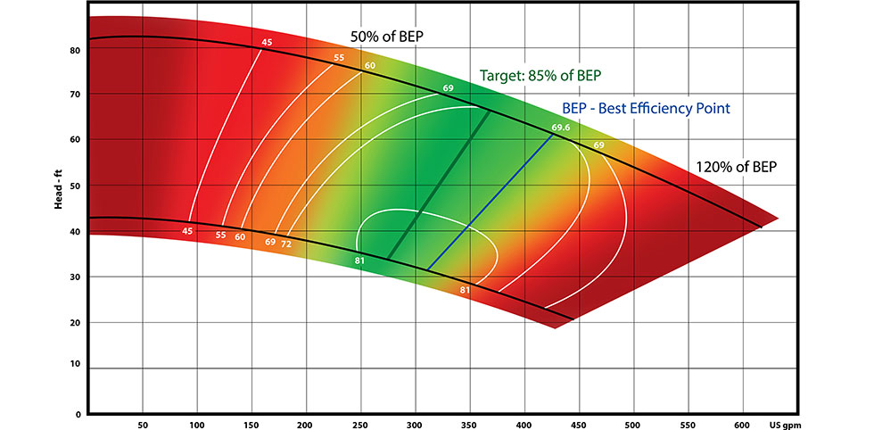
With a pump selected just at BEP, fluctuations in the flow can result in operation outside the pump’s BEP. From BEP, it only takes 20% movement to go too far out on the curve, creating the potential for cavitation and increased radial loads.
Therefore, it may be best to target selections at around 85% of BEP. This allows system fluctuations of 35% to the right and left of BEP, without moving out of the acceptable 50% to 120% window.
In Image 3, the optimal range of operation on the pump curve is shown. The area in green encompasses that 50% to 120% window, with pump operation becoming more unstable as you move out into the red on either end of the curve. Note the short distance past BEP before the pump would enter nonoptimal and potentially problematic operation.
Selecting the Optimal Pump for a System
Now that the range of optimal operation on the performance curve has been established, selecting an optimized pump becomes more achievable.
Often, it is not enough to select a pump based on just one specific flow and head. Rather, the range of conditions that the pump will experience during its operation should be considered. A centrifugal pump is a dumb device—it has no sensors or process controls. It is simply going to move as much fluid as it can.
The amount of fluid moved by the pump is limited by the resistance to the flow, the physical capacity of the pump, and the amount of flow that can enter the pump. The pump simply spins and moves fluid with no regard to the intended flow rate or desired pressure.
For instance, if a system includes a filter, the design point extremes presented by the presence of this filter would be when the filter is clean and when the filter is dirty. This swing could be 15 pounds per square inch (psi) (~40 feet total dynamic head [TDH]) or more in differential pressure drop across the filter.
In a system designed to produce 30 psi (~70 feet TDH), a 15 psi (~40 feet TDH) pressure swing is huge.
As an example, if an application requires 100 gallons per minute (gpm) at the end of the piping system, then the pump design must be able to overcome all the losses within the piping system, including a potentially dirty filter. Assuming the entire system has a loss of 40 feet with the filter clean and 70 feet with the filter dirty, then the pump engineer needs to size for both scenarios: 100 gpm at 40 feet TDH and 100 gpm at 70 feet TDH.
However, the pump will produce more flow at the lower head conditions. As flow goes up, the friction loss will go up as well. Therefore, it will take some recalculation of the system losses at higher flow rates to arrive at an estimate of the higher flow operation point. Both condition points should be within the 50% to 120% of the BEP window, if possible.
During system design and pump selection, because the full range of real-world operating conditions can never be fully known or predicted, it is common practice for system engineers to “pad” expectations to accommodate this variability.
If 100 gpm is required by the application, 20 gpm might be added for a safety factor, resulting in the selection of a 120 gpm pump. Further, if a design challenge is known, like the potential of a dirty system filter outlined in the scenario above, 20 feet TDH might be added to the pump requirement on top of the 70 feet.
With this padding, the system designer might specify a pump to produce 120 gpm at 90 feet TDH. The problem arises when the pump is installed into the system and the system does not give the resistance to fluid movement anticipated. The designer ends up with more flow than anticipated and the pump may operate well outside the desired efficiency window.
Operating a Pump for Optimal Performance
It is the variability in the system itself that creates many bad pump installations. In many cases, not all the system conditions have been accounted for or adequately predicted. If this is the case, the pump may run in condition areas outside of the recommended 50% to 120% of BEP window. Further, net positive suction head required (NPSHr) and minimum submergence need to be met at all operating points.
When a pump operates outside the recommended window, bad things happen: suction or discharge side cavitation, excessive vibration and air entrainment. Often it is a combination of these things, all of which put undue strain on the pump.
In high-flow conditions (greater than 120% of BEP), maintaining NPSH can become a problem given that NPSH available (NPSHa) decreases and NPSHr of the pump increases as flow increases. Radial side load on bearings also increases rapidly in high-flow conditions.
In low-flow conditions (less than 50% of BEP), the pump is still trying to move a lot of flow, but restriction in the system forces a portion of the flow back from the high-pressure side (discharge) to the low-pressure (suction) side of the pump. This reverse flow causes excessive turbulence and vibration in the pump. Low-flow conditions can also cause radial side load on bearings to increase rapidly.
These scenarios often result in premature failure of the mechanical seal, shaft coupling, bearings and metal parts. Parts failure is rarely indicative of the quality of the parts, or even the initial sizing and selection of the pump, but rather the operating conditions of the pump.
Designing for Extreme Conditions
Pump selection involves a series of tradeoffs. In clear water applications, necessary tradeoffs are minimal. Most centrifugal pumps can move clear water and will usually do so at the intended flow rate and pressure. In optimization, the goal is to select a pump with great efficiency (meaning few losses) and a pump that operates reliably.
In nonclear water and other challenging applications, high solids content, large solids, entrained air, or unusual suction conditions prevent selection of a typical centrifugal pump.
In these systems, the conditions will fluctuate greatly from the intended flow and pressure.
Under these more difficult conditions, there will likely be a tradeoff in lower efficiency to get the design features necessary to operate in those conditions.
In these applications, strainers, choppers, hardened materials or rubber-lined offerings may be required by the demands of pumped fluid and subsequently cause the pump to operate less efficiently.
If extreme condition swings cannot be minimized, the optimal choice may be to go outside standard system design. Sealless pumps, vortex pumps and variable speed drives are all options more forgiving of wide operating conditions.
Sealless pumps
Mechanical seal failure is one of the most prevalent reasons that pumps are pulled out of service for repair. Some pump industry professionals estimate that 85% of pump repairs result from failed mechanical seals.
Mechanical seals are at risk of damage in bad applications with movement, vibration, temperature swings, air entrainment and process buildup. Sealless pumps eliminate this problem component altogether, instead employing an enclosed column design to replace the functionality of a mechanical seal.
While not suitable for every application (such as systems with pressured inlets), vertical sealless pumps operate successfully in a wide variety of challenging applications—even those with high solids or with high temperature fluids.
In this instance, the tradeoff is minimal. The major upside in maintenance cost and reliability makes up for any initial retrofit cost.
Vortex pumps
Vortex pumps operate in a wider window than typical centrifugal pumps. Due to their design physics, they can handle a certain amount of entrained air and solids. In operation, they create little radial loading on the shaft and bearings, even under extreme operational conditions.
However, there is a large impact on pump efficiency, often 30% or more, compared to typical pumps.
In many cases, this loss of efficiency is an acceptable trade-off for longer pump service life.
Variable frequency drives
Variable frequency drives (VFDs) allow for more flexibility in operation by regulating the speed of the pump. Often this speed change can ensure pump operation remains inside the recommended BEP window. In the previous example, a lower speed may help the designer keep the pump in the optimal operational window, even at the lower resistance/higher flow condition of a clean filter.
Inclusion of VFDs cannot solve all problems, but it does mitigate the effects of changing operational conditions within a system. In some applications, the purchase and installation cost is an acceptable tradeoff for more trouble-free operation.
Optimization Is Not One Size Fits All
There is little consensus on what constitutes an optimized pump because it is specific to the goals and operating conditions of each application. Having a clear understanding of the BEP range and real-world operating conditions will result in the proper alignment between initial cost, energy consumption, maintenance requirements and life span and produce a fully optimized pump for each installation.
