

When looking at commercial building energy usage, space cooling is one of the largest consumers of electricity. Central cooling is used for large buildings where a chilled water plant can consume 20% to 30% of a building’s total electrical energy. Pumps are required to distribute the chilled water to the building's air handling units.
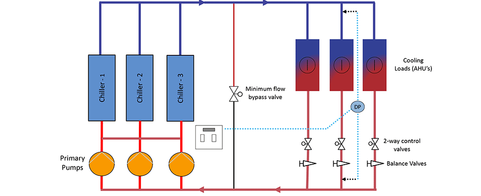
Currently, the most common chilled water design is a variable primary flow (VPF) system. A simplified example of this design is shown in Image 1. Water is pumped through the chillers, distributed out to the building’s air handling units and then returned to the pumps. With this design, the pump head must be sufficient to overcome the frictional losses through the chillers, the piping, the air handling coils, the control and balancing valves. The most common control method for the variable speed pumps is pressure control via a differential pressure transmitter strategically located in the piping system. When a constant differential pressure is maintained, adequate pressure and sufficient flow is supplied to each air handling unit. When the chilled water flow demand from the air handlers is lower than the chiller’s minimum flow requirement, a bypass valve must be opened to provide protection to the chillers.
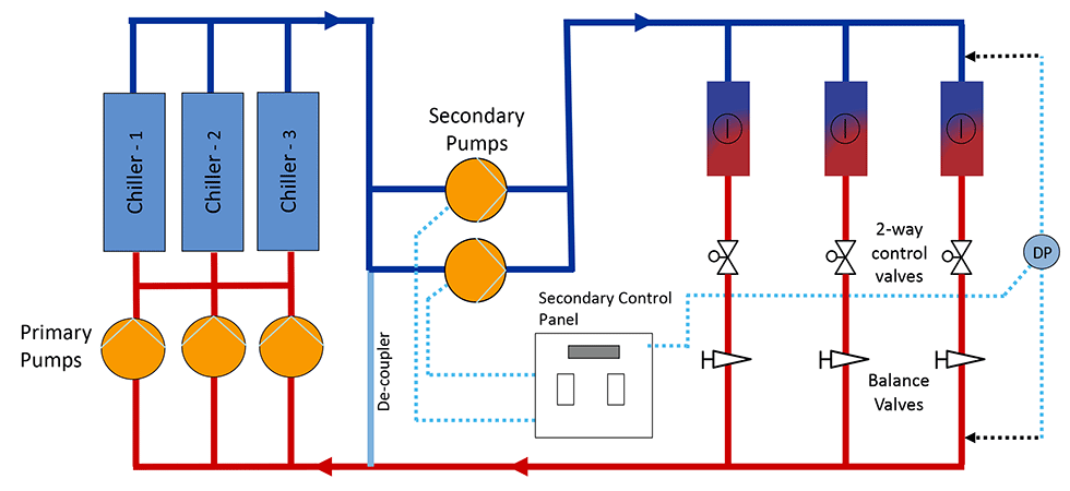
Prior to VPF designs becoming more prevalent, primary/secondary systems were the standard for chilled water systems and are still a design consideration today. A simplified example of a constant primary/variable secondary system is shown in Image 2. This type of design requires two sets of pumps. The primary pumps supply water through the main chiller loop. These pumps need to only provide enough head to overcome the pipe, fitting and valve losses along with the pressure losses through the chillers. The secondary pumps distribute water to the air handling units where the pump head must overcome the frictional losses through the piping, air handler coils, control and balancing valves. Much like the VPF system, a differential pressure transmitter is installed at a strategic location to maintain sufficient pressure, ensuring adequate flow for each air handling unit (AHU).
Ensuring Adequate Flow to Air Handling Units
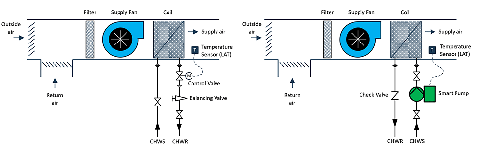
Both VPF and primary/secondary systems involve the use of control and balancing valves to ensure proper flow to each air handling unit. Image 3 shows a typical coil piping arrangement for an air handling unit. A constant leaving-air temperature (LAT) is maintained by use of a modulating control valve. An increase in the return air and/or outdoor air temperature will cause an increase in the leaving air temperature, which will require additional cooling flow in which case the control valve will modulate to a more open position. Similarly, a decrease in return air and/or outdoor air will result in a decrease in leaving air temperature and the control valve will modulate to a more closed position.
To ensure proper flow to the coil, the pump must provide enough head to overcome the pressure losses through the coil, control and balance valves. A pressure drop must exist across a control valve if flow is to occur. If the pressure drop across the valve when fully open is not a large enough percentage of the total system head loss, there will be little change in fluid flow until the valve actually closes. Control valves must be selected to align with the performance of the cooling coil if good control is desired. A common rule of thumb to ensure good control is to select valves such that at design flow, 25% to 50% of the total system pressure drop be absorbed by the control valve. Undersized control valves can result in good valve authority/good control but may not be able to provide sufficient flow during peak demands, while oversized control valves can result in poor control.
Distributed Pumps
One way to avoid challenges with control and balancing valves is to eliminate them. Image 4 shows how the control and balance valve can be replaced with a smart pump with integrated controls. With this design, the same temperature sensor that was connected to the control valve can now be connected directly to the pump. The smart variable speed pump can adjust its rotational speed to maintain the leaving air temperature set-point. It is literally performing the same function as the control valve but at a much lower operating pressure. The check valve prevents any backflow to the supply side should the AHU not be in use. An analogy to the difference between the two is that the control and balance valves represent the brakes in an automobile, and the pump represents the gas pedal (accelerator). Instead of applying both the accelerator and brakes, the smart pump simply applies the amount of gas needed to maintain the speed or setpoint in this case.
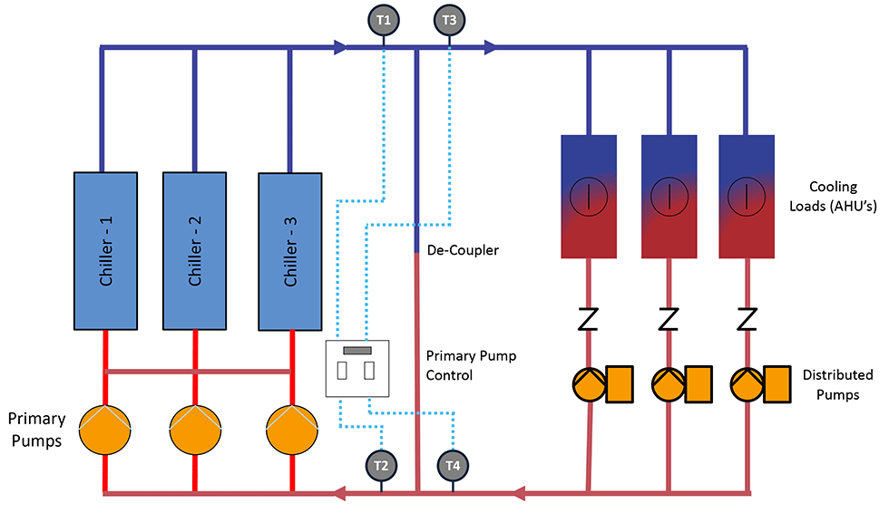
Image 5 shows an example of a distributed pumping system. The system is similar to a primary/secondary system apart from having the centralized secondary pumping system. In this case, the flow from the decoupler is handled by the smart (distributed) pumps. The distributed pumps are sized to overcome the friction from the supply side of the decoupler to the AHU as well as the return side of the decoupler. The primary pumps need only overcome the friction through the primary piping loop and the chiller. The control of the primary pumps is based on temperature. There are four temperature sensors, two on each side of the decoupler. The primary pump control should be set up such that there is no flow through the decoupler when there is sufficient cooling load. If the delta-T on the load side (T4-T3) is the same as the delta-T on the chiller side (T2-T1), there will be no flow in the decoupler. This means that the chilled water flow is matching the required flow to handle the load. Essentially the controls are set up to maintain a zero delta-T between the supply and return on both sides of the de-coupler. In this case, the system will be in perfect balance without excess flow to the chillers. This results in optimal chiller performance, and low delta-T conditions are avoided. The use of distributed pumps can save chiller energy, which can be more than the pump energy savings. The control should also have a chiller protection control mode for low flow periods. This can be accomplished by monitoring chiller differential pressure or using a flow sensor. When the chillers minimum flow is reached, the primary pumps will maintain the required speed to protect the chiller until the chilled water demand increases.
The use of smart distributed pumps in this manner has several advantages.
The system is self-balancing, so there is no need for balancing or control valves of any kind. This cuts time and expenses during the test and balance process.
Improved chiller delta-T as smart pumps are precisely matching the load, so no over-pumping can occur. Additionally, many smart pumps have a flow limiting function.
Connected pump horsepower is lower as each pump is sized for individual coils, and there is no control or balancing valve. A control plus balancing valve will typically have a pressure drop between 5 to 10 pounds per square inch (psi).
Pump energy will be lower as there is no need to maintain a minimum system differential pressure. Pump efficiency will be nearly constant as the distributed pump will follow a friction only system curve with no fixed head. Pump energy savings can be 50% to 80% over a conventional system.
Flow can be controlled instantly with the distributed pump, so control is precise and there is also no fear of over-pressurizing control valves which reduces their controllability.
Lower installed cost than a primary/secondary system due to elimination of control valves and lower pump horsepower (can be slightly more expensive than a VPF system).
With recent advancements in pump technology and VFD reliability, there are few disadvantages of distributed pumping, but some are worth listing.
All coils must have a pump. For critical applications where redundancy is required, a duplex pump arrangement or alternative distribution design may be required.
Smart pump size range: small circulator pumps below 5 to 10 gallons per minute (gpm) rarely have on-board controls equipped to take in an air temperature signal and maintain a leaving air temperature. However, control valves are rarely used in flow ranges below 10 gpm, and in those cases, fan coils with simple on/off valves are used in which case a differential pressure controlled smart pump can be used to provide flow for a group of fan coils.
The concept of distributed pumping is not new. It has been discussed for at least 15 years. Ten to 15 years ago, this solution was considered cost prohibitive based on individual component costs of pumps, motors, drives and sensors coupled with the installation labor and commissioning. Pumps today can be equipped with integrated controls, pressure and temperature sensors and easy connectivity to building management systems. Inline pumps with permanent magnet/electronically commutated motors and wet rotor designs offer superior efficiency and maintenance free operation that often have the same installed cost as modern integrated control and balance valve solutions.
References
Steven T. Taylor, Optimizing Design & Control of Chilled Water Plants Part 1: Chilled Water Distribution System Selection, ASHRAE Journal, July 2011
Sam K.H. Lam, Chris Tham, Sunil Saseedharan, Liong Yin Churn, Adrian Wang, Distributed Pumping Chilled Water Hydronic System for Air-conditioning Systems, July 2017
ASHRAE Handbook I-P Edition 2016, Heating, Ventilating, and Air-Conditioning Systems and Equipment
