

Dynamic balancing is an important concern during the repair of most rotating machinery, including pumps and electric motors. Failing to detect and correct excessive imbalance at this stage can undermine repair efforts, allowing persisting vibratory forces to attack bearings and deteriorate machine foundations. With pump rotors and impellers, it is also necessary to recognize that different dynamic balancing methods apply than for electric motor rotors, due to differences in their construction.
For example, the mass of electric motor rotors is between the bearings, whereas many pump impellers mount in overhung configurations. Electric motor rotors are also longer than their diameters, while impellers typically have a narrower length-to-diameter profile. The narrower profile may require special rules allocating allowable residual imbalance per International Organization for Standardization (ISO) standard 21940-11 and special balancing machine techniques.
Is Balancing Always Necessary?
When evaluating a pump’s condition during the repair process, the technician must decide whether to check/correct the impeller balance in the balancing machine. Usually, it is impractical to check vibration levels by test running a pump before repair, and arbitrarily checking the dynamic balance of every pump would unnecessarily inflate the cost of some repairs. If an impeller is not worn or damaged, and the need for repair is unrelated to machine vibration, the cost of checking the impeller balance may not be justified. Note, though, that impeller imbalance is known to cause some pump shaft and impeller retaining bolt failures, so decisions about checking imbalance should weigh these possibilities.
Balancing Setups
Balancing pump impellers on the pump shaft as an assembly is common practice but often results in overhung configurations that present challenges to the balancing process. Since the shaft itself can hardly be out of balance, however, a common method for multi-impeller pumps is to balance each impeller on a mandrel before assembly on the pump shaft. When calculating allowable residual imbalance tolerances, consider the rotor’s total weight. Basing the calculations solely on impeller weight may yield lower tolerances than necessary.
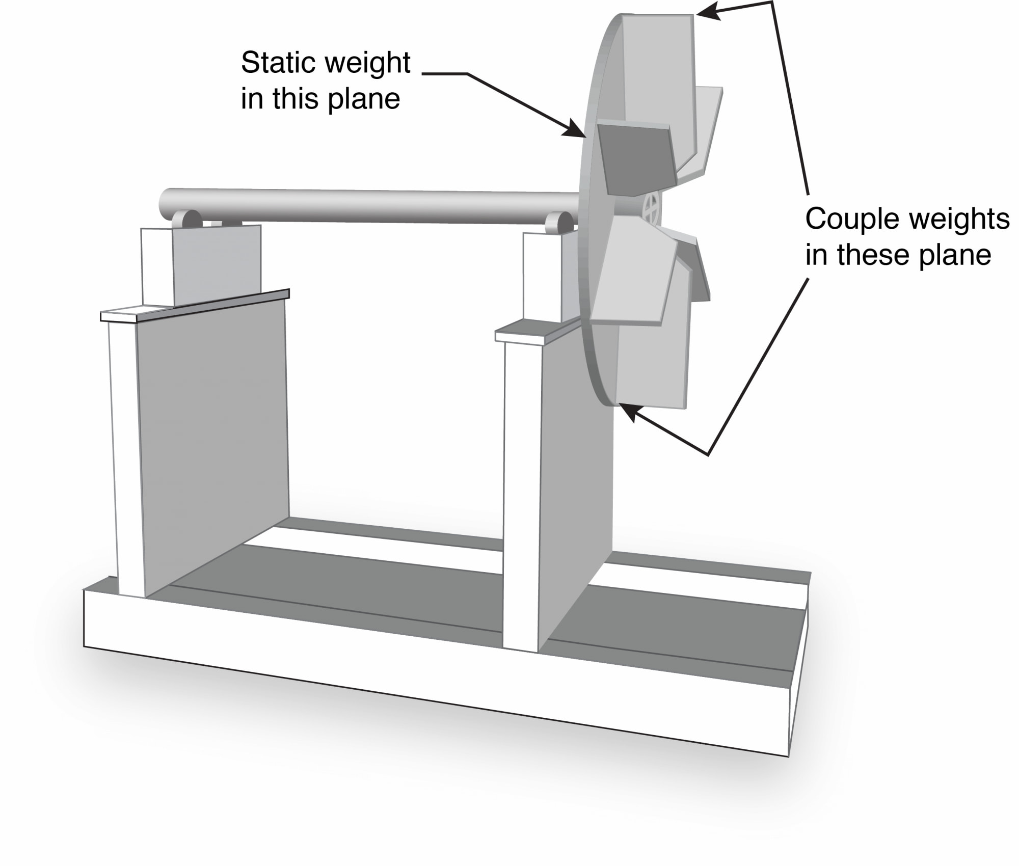
Single-Plane vs. Two-Plane Balance
The next decision is whether to use a single-plane or two-plane balance. An old guideline not shown in the current ISO standard 21940-11 said single-plane balancing was acceptable for rotors with a length-to-diameter ratio less than 0.5 and rotating speed below 1,000 rotations per minute (rpm). Although most pumps operate above 1,000 rpm, many pump manufacturers only balance impellers in a single plane. That is fine if they control the manufacturing process to minimize “couple imbalance” but numerous instances show this is not always the case. Once the impeller is in the balancing machine, checking the balance in two planes is recommended (Image 1).
Making Balance Corrections
Balance corrections on pump impellers entail removing weight, usually by grinding on the impeller shrouds and then smoothing the affected areas. Drilling holes to remove weight is discouraged because the holes will generate localized turbulence in the pumpage.
Since it is difficult to “ungrind” a correction weight, make the initial correction by attaching putty to the impeller. When acceptable balance is achieved, grind the correction weights 180 degrees from the putty location. If the initial balancing with putty calls for a large amount of correction weight in a couple configuration, evaluate whether two-plane balancing will be practical.
Large couple imbalance usually results from casting and machining anomalies in the manufacturing process. Again, manufacturers try to control these anomalies, so they only balance impellers in a single plane. When it is impractical to correct a couple imbalance on an impeller, the impeller is often “bad” and needs replacement. It is recommended to balance the pump impellers to G2.5 per ISO standard 21940-11. Special balancing procedures apply to high energy pumps as defined by the American National Standards Institute (ANSI)/Hydraulic Institute (HI) Pump Standards.
Vertical Turbine Pumps & Split Case Pumps
Two types of multistage pumps are common in the industry: vertical turbine pumps (VTPs) and split case pumps. When multistage pumps require balancing, each impeller should be two-plane balanced individually on a mandrel. After reinstalling the impeller on the pump shaft, ensure that the assembly is within the G2.5 tolerance. Beyond this, the procedures for VTPs and split case pumps differ.
VTPs. For VTPs, match-mark the impeller and any mounting collets or hardware. After the final balance check, disassemble the rotor in preparation for proper assembly in the pump bowls. If the balance of the assembled rotor is out of spec, check the shaft runout and impeller mountings. Some slight trim balancing can be done on the assembled rotor, but excessive imbalance indicates a problem that needs correction.
Multistage split case pumps. For multistage split case pumps, assemble the rotor for final assembly in the casing with any stage bushings or other stationary components that mount between the impellers. Make sure the shaft nuts that hold the impellers in place are just snug, not tight.
Before spinning the rotor in the balancing machine, tie the stationary components to the machine’s base with string. This (and a little machine oil between them and the shaft) will prevent them from rotating. After confirming the assembled rotor balance is within tolerance, tighten the shaft nuts and recheck the balance. Any notable change in the rotor balance with tight shaft nuts is likely due to runout of the shaft sleeve or impeller axial faces. Such runout will cause the shaft to bow when the shaft nuts are tightened.
A good understanding of static-couple balancing and the procedures for multistage pump rotors is essential for a quality pump repair.
