
The Sabine River Authority of Louisiana created the Diversion Canal System in 1970. The goal was to decrease dependence on the sole area aquifer and supply fresh, untreated surface water from the Sabine River to industries in the Lake Charles and West Lake area, which includes petrochemical plants and an oil refinery. Because of their proximity to the Gulf of Mexico, the surrounding surface water is brackish and unsuitable for the process requirements of these plants. The system consists of three pumping stations, five level control gates, nearly five miles of underground pipeline and more than 35 miles of channel canals. Pump Station 1 draws water from the Sabine River into the canal system. Pump Stations 3 and 4 pump the water into the pipeline for delivery. It is used as utility water, process water or steam generation by Air Liquide, Air Products, Citgo Phillips 66, Eagle US 2, Entergy, Equistar, LC Co-Gen, LA Pigment, Lyondell, Matheson Tri-Gas, Westlake and Sasol. According to a 2014 report by the Southwest Louisiana Entrepreneurial and Economic Development (SEED) Center, the system is under contract to deliver 141 million gallons per day (mgd) to these thirteen major users, with a total capacity of 216 mgd.
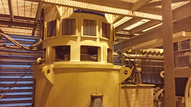 Image 1. An eddy current drive mounted on a vertical turbine pump at the Sabine River Authority (Images and graphics courtesy of DSI/Dynamatic)
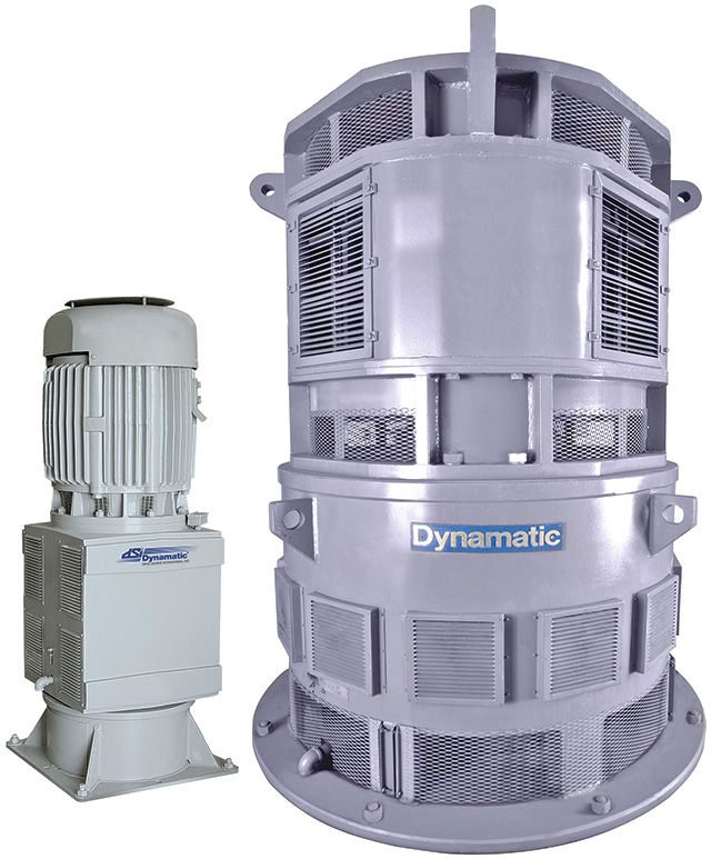 Image 2: An Eddy Current Drive
Why Variable Speed?
Eddy current drives and VFDs provide controlled, adjustable speed to alternating current (AC) motor-driven pumps. By adjusting the speed of the pumps to match the necessary capacity, the shaft load of the pump can be reduced, resulting in significant energy savings in the form of reduced electrical power input. With large industrial pumps, the savings can be well over $100,000 per year for each unit in operation. Variable speed operation also reduces wear on the pumps and reduces possible hydraulic fluctuations in the pipeline system.What is An Eddy Current Drive?
VFDs operate by electronically altering the input power (frequency and voltage) to control the speed of the motor. Eddy current drives—also known generically as magnetic drives, eddy current clutches or magnetic clutches—are driven at a constant speed by an AC motor and use a simple electro-magnetic device to control torque and speed to the driven load. The power to the motor—and to the pump—is not manipulated electronically. Instead, it comes directly from the electrical bus. This prevents harmonic distortion and other power quality problems. The electrical system sees only a constant speed motor operating at a varying level of loading.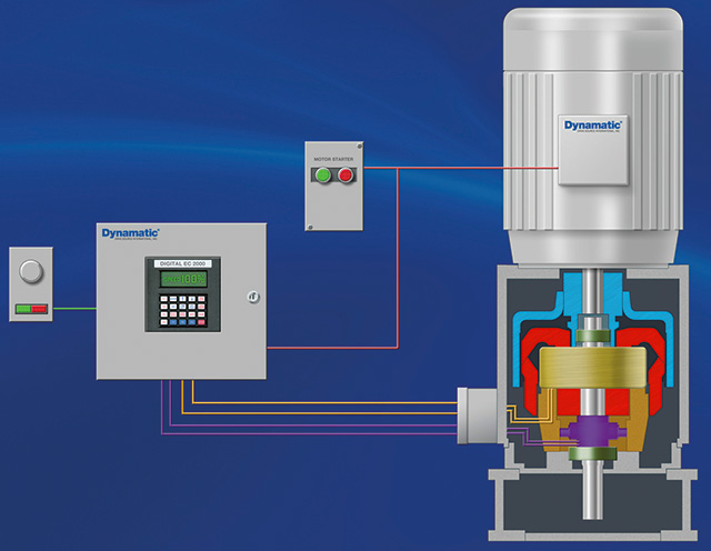 Figure 1. In a typical configuration, an induction motor is mounted on top of the eddy current drive
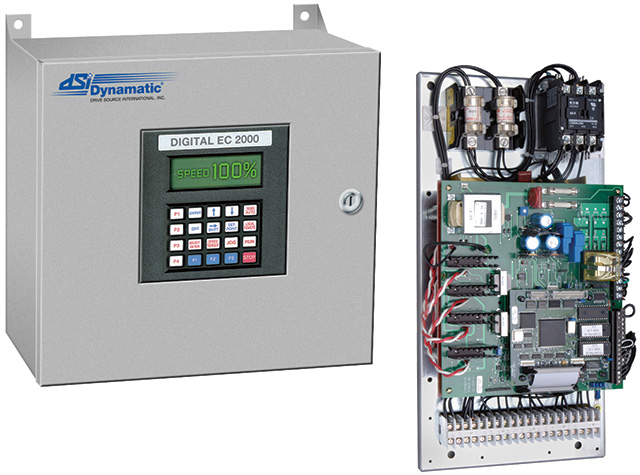 Image 3: Typical digital eddy current drive exciter/controller