

Part 1 of this article appeared in the February 2022 issue of Pumps & Systems.
Passing Vane Cavitation Phenomena
This is a unique and specific type of cavitation caused by the impeller passing too close to the cutwater(s) on a volute-style pump, or in the case of a diffusor-style pump, the leading edge of the diffusor vanes. When the clearance between the impeller and the cutwater is too small, the liquid pressure will be reduced as a result of the increased velocity (think of the pressure-velocity effect as explained by Bernoulli’s equation and note this is a very localized phenomenon). When the pressure is reduced, it is possible to drop below the vapor pressure of the liquid—consequently, the liquid will flash to vapor. Once the generated vapor bubbles move past the low-pressure area, they subsequently, violently collapse as they enter the neighboring higher-pressure area. The vapor bubble collapse will cause local cavitation damage.
The cavitation damage will manifest near the cutwater area on the volute and the tip of the impeller vanes. The damage is typically in the center of the vane and away from the shrouds.
In an effort to determine if this passing vane syndrome is the root cause of your pump issues, know that the passing vane pulses possess the two very measurable and discernible properties of frequency and amplitude. You can utilize this information for your investigation.
Finally, it is important to note that the cavitation damage is caused by a related, yet separate, phenomenon from the simultaneous mechanical pressure pulses previously mentioned. Just as important as overloading the vanes are the pressure pulses that transmit mechanical shock via the pump shaft to the bearings and mechanical seals. When you can’t figure out why your antifriction ball bearings and seal faces are short lived, this may be one of the top reasons. The shock waves create damage to the ball bearing surface and the race. Shaft deflections caused by the pressure pulses will create mechanical seal face issues. It is rare that the pulsations create any sort of shaft damage. A good vibration technician can easily pick up on this issue with simple instruments.
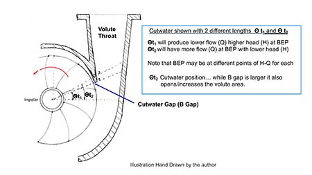
Trimming the cutwater back (shortening) to achieve the desired B gap clearance will also change the best efficiency point (BEP) for the pump by moving it further right on the curve. Another way to think of this is the flow rate will be higher at BEP. The modest downside of this approach is that you may (depending on the overall volute shape) lose a few feet of head at BEP and perhaps 1% efficiency. To most operators/owners, the changes will not be noticeable.
Some manufacturers have experimented with slotting the cutwater to steepen the pump (H/Q) curve and reduce drooping as the pump approaches shutoff. During casing inspection and maintenance evolutions, you may not need or want to reestablish the eroded cutwater to its original location. The leading edge should be reestablished because the worn V shape and uneven edges lead to turbulence.
Experience has shown it is better to have a larger cutwater clearance (increase the B gap) than it is to just trim the impeller to a smaller diameter to mitigate the pressure pulsation issue. That is, start with the correct design clearance in the first place. Trimming the impeller will (theoretically) reduce the efficiency of the pump, but the resultant and unintended issue is that the amount of impeller vane overlap also decreases. As vane overlap decreases, the possibility for both discharge and suction recirculation issues increases.
The suggested range of clearance between the impeller and cutwater can vary from as little as 4% to 12% with the midrange values of 6% to 10% as the norm. These ranges are based on industry best practices and accepted institutional engineering specifications and standards.
Please keep in mind my comments are general and the magnitude and veracity of the prescribed effects depend on the pump design, specific speed, energy levels and operating parameters. A single volute pump at 20 brake-horsepower (BHP) and 4 pole speeds will have different results from a multistage diffusor pump at 500 BHP and 2 pole speeds. Additionally, your company’s engineering standards and design criteria may not permit the use of maximum diameter impellers. To be clear, I am not saying it is acceptable or desirable to just open the clearance to magnitudes beyond the recommended 12% to 14% because there are other side effects besides the loss of efficiency and potential recirculation—one of which is additional axial thrust vibration issues.
Say you don’t want to trim the impeller for an existing design. Contrary to many designer opinions, I would suggest it is not always a bad thing to trim the cutwater back a little (not too much) to gain the desired clearance. Trimming the cutwater adds more volume to the throat area and reduces the cutwater turbulence enough that the resulting reduction in turbulent flow counteracts and balances the equation for the theoretical efficiency loss.
Odds vs. Evens
If the number of impeller vanes and cutwaters is an even number, you should increase the B gap clearance from 4% to at least 10%. If possible, complete the change in two steps versus one with a review after the first step.
Note: You can have more than one cutwater such as a dual volute or the pump may be a diffusor style with numerous stationary vanes. If you have a dual volute pump, you should use an impeller with an odd number of vanes. If not, then the clearance should be increased.
Also, you can have the proper clearance and still have vane passing frequency issues due to the vane tip exit geometry, usually because the edges are too squared or blunt. This can be corrected by underfiling the impeller vanes—sometimes referred to as “sharpening the blades.” You can sometimes correct the issue by overfiling the vanes on the discharge side.
The cutwater thickness (t4) is often designed to be kept as a constant ratio to D2 (impeller diameter).
Some experienced designers suggest the ratio should be near 0.006, which is a little skimpy for my conservative design tastes and some higher energy or robust applications. Nevertheless, it is a minimum starting point.
Cutwater angle and projection/length are subjects perhaps too tedious for this forum. Realize these decisions need to be made with complete consideration for the impeller and casing design, which includes the throat. For a given impeller and casing design, simply changing the cutwater geometry will markedly change the pump performance.
