

Last month, I pointed out that the pump casing does not receive the same level of respect as the impeller. Further, it takes both the casing and the impeller working jointly to make the pump perform effectively and efficiently. The size and geometry of the casing are just as important as the impeller design. How they are matched is paramount.
I briefly mentioned the casing cutwater in the column where I stated that the cutwater is also referred to as the flow divider, tongue or splitter. The placement of the cutwater, its length, thickness, leading edge profile and flow angle all have important roles in the casing efficiency and, hence, overall pump performance.
Traffic Control
First, a few somewhat rhetorical questions to facilitate the mindset. Imagine you are driving on a busy interstate highway and the road sign indicates your exit is coming up in 1 mile. Do you immediately start to slow down or do you maintain your speed until you actually get to the exit ramp? Do you wait to brake until you are in the deacceleration lane or before? Is the exit ramp single or multilane? Is the exit ramp curve a gradual radius and banked (positive camber) so you don’t need to jam the brakes? Is there a stop sign or traffic signal at the bottom of the ramp? Or does the ramp simply blend as a confluence with the crossroad? Do you understand that your driving decisions and subsequent actions affect the other vehicles around you? Are your driving decisions based on the design of the highway?
You may think I am a little crazy, but the science of traffic control for a given number of vehicles per lane per mile (flow rate) is dictated by the design of the road (the pipe). Facilitating traffic flow on a highway is analogous to liquid in a pipe, and the formal discipline of traffic management actually follows many of the same rules of motion. Mechanics and fluid dynamics equations for pumps and systems are also used by civil engineers to design roads. Traffic engineers use the same formulas, but they haven’t figured out yet how to factor people into the equation (i.e., driver personalities, distractions and emotions).
If you haven’t already guessed, in my earlier example the pump cutwater is synonymous with the decision point to exit onto the off ramp. Are you getting off the interstate or are you staying on? How you approach the exit (the volute throat) affects both the traffic behind you and the entire local highway system, but how you, as the driver, approach the exit also depends on the highway design.
Casing to Impeller Clearance
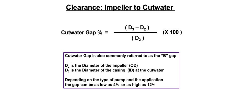
For an expanding volute pump where the impeller centerline is offset from the casing centerline (i.e., noncongruent), the clearance between the outer diameter (OD) of the impeller (D2 dimension) and the cutwater is a critical design parameter. The clearance is also referred to as the radial gap. The impeller OD to casing clearance is typically at its lowest magnitude in the area of the cutwater. I am specifically referring to the clearance from the vane tip to the cutwater and not the impeller shroud. This tip clearance is often referred to as the B gap. (The clearance between the impeller shroud(s) and the cutwater is the A gap.) If the B gap clearance is too close, the tip of each impeller vane will create an undesired pressure pulsation (hydraulic shock) as it passes by the cutwater.
Side note: Because liquid is noncompressible, there are resultant pressure waves or pulsations as each vane tip passes in close proximity of the edge of the cutwater.
The pulses are audible and contribute to overall pump inefficiency—they manifest as extraneous noise. This pulsation phenomenon is commonly referred to as “passing vane frequency.” The pulsations also create secondary hydraulic shock waves that travel upstream through and to the suction side of the impeller. These shock waves may even create issues with maintaining the laminar flow required to load the suction side of the impeller properly.
The closer the cutwater gap, the higher the magnitude of the pressure pulsations. The pulses will also create flow recirculation issues in the area of the vane tips that will reduce the capacity of the pump. Even at minimum impeller diameter you will have pressure pulses from the vanes but the magnitude is acceptable. The magnitude of the pulse increases with rotational speed and departure in either direction from the best efficiency point (BEP).
Should you decide to reduce the impeller diameter to mitigate the magnitude of the pressure pulse issue, there will be a corresponding loss of pump efficiency. In every pump design there is compromise, and so there is also a “Goldilocks” amount of clearance (not too far and not too close) where you can achieve the desired efficiency without the deleterious effect of the pulsations.
The compromise to obtain the proper gap dimension depends on the type of pump and the speed, consequently there is not a hard and fast thumb rule to preclude or mitigate the issue. However, a general guideline would be the formula where we consider the ratio of the impeller diameter to the casing diameter at that point of closest proximity to the cutwater (see Image 1).
The pressure pulsations may also cause damage to the impeller vanes. Each pulse acts to stress the working side (pressure side) of the impeller vane.
The vanes are already under a significant amount of torque just doing their assigned task, and so the added stress of the pulsation can cause the tips and associated shrouds to break off, especially on high-energy pumps.
