CFD and engineered improvements assist designers in their quest to produce more work from less energy.

Pumping fluids with sediment, chemicals, slurry and inks has always been an air-operated double diaphragm pump’s (AODD) domain. Offered in many different construction materials, AODDs can be built to pump virtually any fluid, in most volumes.

AODD pumps are the picture of simplicity. Diaphragms move inside fluid chambers to intake and expel fluid while check valves keep the fluid motion flowing in the right direction. These pumps operate solely by the back and forth oscillation of a single rod connected to two horizontally opposed diaphragms. How is the rod moved?

Powering the Pump

While multiple options for powering a diaphragm pump are available, pneumatic is the most common and typically optimum for most installations and applications. The humble beginnings of compressed air date as far back as 2000 B.C. when bellows were used to stoke the flames, as man forged iron and steel into the shapes upon which he would build his future. Today, the modern uses for compressed air are staggering. Everything from dental tools to modern robots relies on compressed air power.

Engineering Air Flow

Efficiency is critical in any air-operated appliance. Compressed air is used so extensively in the industry that it is often regarded as a fourth utility—such as electricity, natural gas and water—but when evaluated on a per unit energy delivered basis, it is the most expensive. Therefore, an AODD pump that performs at lower pressures saves energy (and money) by consuming less compressed air. It also makes more air available for other equipment.

Converting pneumatic energy to mechanical energy in the most efficient manner is the engineer’s goal. Installing sliding valves and seals that direct the air as desired is easy, but the real engineering occurs when determining how much air should go where, when and for how long. An engineer must decide whether to fall back on old technology or forge ahead into uncharted theoretical territory in search of the next great breakthrough.

Often, to perform a complex task, engineers will design a complex circuit. One chemical transfer system provider decided to keep it simple, with fewer moving parts.

Engineering Down the Rabbit Hole

A team of chemical transfer pump engineers tried a different approach, starting with where the air enters the pump and begins its work. This chemical pump provider wanted to address common problems experienced with AODD pumps—such as freeze up, stalling and lack of efficiency.

Air motor cross section
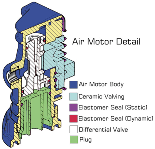
Figure 1. Air motor cross section

Air entering the pump first moves into the major valve and actuates the differential piston. The design of the piston, with one end of the piston larger than the other, means that when air is applied, the piston will always go down first. This motion applies air to the major and pilot valves.

A key feature in the design is the integration of the major valve and pilot valve into the same ceramic plate, a design that means significantly fewer moving parts. Ceramic is basically rock, and it wears like rock, so the engineers manufactured the major and pilot valves from ceramic for extreme durability. The ceramic pieces were ground to extremely tight tolerances, which provide precise air management, decreasing the need for other parts and seals. The end result was an air management system built essentially from stone that has only four moving parts (see Figure 1).

Fewer parts mean less maintenance, simple operation, and less wear and tear. This simplified design also provides efficiency of operation. Minimizing moving parts and dynamic seals decreases the possibility of leakage as well.

Air entering the differential valve chamber presses the differential valve down, allowing air to pass through to the right diaphragm chamber. As the diaphragm chamber expands, air routes back through the ceramic components to raise the differential valve, starting the process to pressurize the opposite diaphragm.

In this air circuit, the only dynamic seals are the two u-cups at the top and bottom of the differential valve. All the other seals involved in the air motor assembly are static in nature, sealing non-moving components. This repeats the theme of fewer wear items to maintain, and less friction from fewer moving parts. Since the ceramic components are ground to such a tight tolerance, they do not require additional dynamic seals to remain air tight.

Exhaust air management is as important as inlet air management. Through extensive 3-D modeling and computational fluid dynamics (CFD) simulations, engineers were able to shape the flow of the exhaust where it enters the pump body (see Figure 2). Once the internal exhaust achieved optimum flow, engineers worked with aerodynamic and thermodynamic analysis. The resulting proprietary development was the virtual end of freeze up.

CFD exhaust air flow
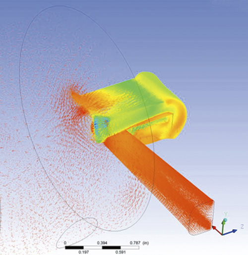
Figure 2. CFD exhaust air flow

This design showed dramatic improvement in efficiency, allowing the pump to start with as little as 6 to 7 psi, rather than the more than 20 psi that is usually required on other models. Depending on the pumped fluid, field testing has shown that this AODD pump moves as much fluid at 20 psi as typical pumps move at 40 psi. The patent pending design addressed the stalling, freezing and efficiency issues that generations of pumps could not.

Challenging Fluid Dynamics

The dynamics of moving fluid are complex. Making the diaphragms move fluid as efficiently as possible is a challenge.

Inlet manifold check valve CFD
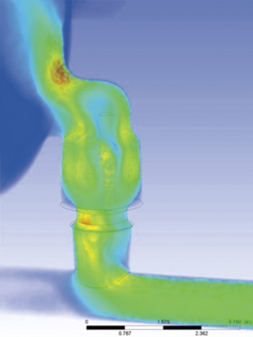
Figure 3. Inlet manifold check valve CFD

Ideally, the maximum possible amount of fluid should be drawn into and pushed out of the fluid chambers with each stroke of the piston, while minimizing (or controlling) small amounts of hydrodynamic cavitation. The diaphragms must have the longest possible service life and be manufactured of many different materials that allow the pump to be used in a wide range of fluids.

Cavitation occurs when the pressure drops below the saturated vapor pressure of the liquid being pumped. Bubbles generate and implode when fluids are subjected to a decrease, then subsequent increase, in pressure. This causes high energy densities, temperatures and pressures to occur at the surface of the bubbles. Vaporization follows, and depending on the fluid being pumped, it even has the potential to freeze or explode.

Designing the fluid chamber, valves and diaphragms using a CFD virtual environment allows engineers to tweak the design to achieve the desired results without costly failed test units. Simulating flow also allows the engineers to see how each change affects the product’s operation.

When maximizing performance and efficiency, the larger the effective piston area, the larger the displacement of the fluid. The effective piston area is mid-point between the backup washer and the seal point of the diaphragm itself.

The engineers also wanted to maximize the diaphragm flex life and have the longest flex hinge possible. They accomplished this by creating a “booted” design, adding length to the convolute form (see Figure 4). The resulting increase in efficiency also helped mitigate cavitation and provided a more uniform fluid displacement, regardless of input pressure, to completely empty the fluid chamber.

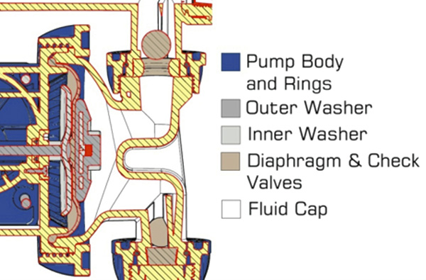
Figure 4. A booted design added length to the convolute form and increased diaphragm flex life.

The search for efficiency is ongoing as engineers continuously seek ways to get more work from less energy. It is clear that as technology advances, so will this search for improved efficiency.