

With high-pressure fluids, there is always an increased awareness for safety. Valves used in high-pressure applications are designed for these pressures, but special care should be taken during packing maintenance. The key to ensuring continued safe operation of these valves is knowledge about the challenges high-pressure sealing presents. These applications can be approachable with the proper tools and understanding of how to maintain safety and reliability.
First, evaluate the application. This is not limited to pressure; temperature is just as important to consider when evaluating the situation. One can first narrow down packing options that function with the expected pressure range but the temperatures seen at that pressure will also be useful. This will help evaluate if polytetrafluoroethylene (PTFE) is acceptable in an application. The temperature threshold for PTFE may be the limiting factor but also check plant specifications. There are many situations where plants have stricter limitations on where PTFE packing can be used.
Actuation frequency and thermal cycling are critical pieces of information when evaluating how best to seal high- pressure valves. When high actuation frequency occurs and/or high thermal cycling conditions arise, using Belleville springs on gland bolts, also known as live loading, is recommended. Live loading reduces load loss on packing even as packing consolidation occurs. This will ensure packing life is optimized and equipment stays up and running longer. When dealing with frequent thermal cycling, it is also critical to evaluate valve stem material. This will be application- dependent, but galvanic corrosion of the stem is more common when temperature cycles are frequent with graphite packing and moisture present. An example of this type of situation is in peaking power plants. In this case, 400 series stainless steel can be more susceptible to galvanic corrosion. Switching to 316SS, which is more corrosion resistant, can help.
Pay attention to bolt materials because they can be important for safety. B7 and B16 bolts have good tensile strength for high-pressure applications; however, tensile strength decreases as temperatures approach 1000 F. Consider other options, like B8M, for higher temperature conditions.
There are some key points to focus on when installing packing for high-pressure valves. Skive cut rings have the ends cut at a 45-degree angle. This is recommended for high-pressure valves to prevent unwanted leak paths. Ensure skive ends meet each other properly, so they are effective. Tamp each ring to ensure everything is seated. This is especially critical because any space will prevent proper packing consolidation, leading to early failure. Keeping the joints 90 degrees apart again helps to limit leak paths. Consider using anti-seize on bolts to ensure proper bolt tension; remember that torque is not tension.
There have been some studies and tutorials to demonstrate that old, rusted bolts use up all the energy trying to move the nut rather than providing the tension desired. Anti-seize ensures friction does not get in the way and the torque applied is actually tightening accurately. Alternating between bolts when tightening helps ensure the gland stays even. A crooked gland can cause uneven consolidation of packing and even damage the valve itself. Performing consolidation cycles is critical to ensure the packing will function properly. It is recommended to perform 10 full actuations, retorque and repeat until less than half a flat (30 degrees) of rotation can be made on the gland nuts.
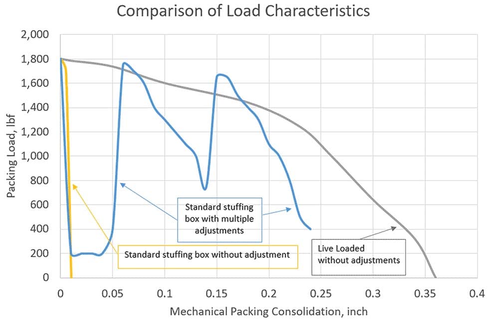
Consider using live loading in areas of high actuation frequency, high thermal cycles, high vibration, difficult accessibility and where components are critical. This is especially useful with control valves. These engineered sets are designed to help reduce packing load decay on the packing based on specific plant situations. Image 1 shows how, as packing consolidation increases, load declines sharply in a standard loading situation. However, Image 1 shows the benefit of live loading because the assemblies with no adjustments only experience slow load decline as packing consolidation increases. This allows for greater longevity from the packing, keeping equipment running longer with less attention from operators. Live loading sets are easy to install and can be designed to fit most equipment.
One style of live loading uses springs and an inner guide (Image 2). Another type uses springs and an outer guide (Image 3). The outer guide acts as a load indicator that helps remove reliance on torque for proper installation. These cartridge-style sets are designed for a specific load; inaccuracies with measuring torque are eliminated with the cartridge because they are designed so the correct load aligns the top washer flush with the top of the cartridge. This visual guide allows for better performance of the assemblies.
.jpg)
Measuring radial and axial clearances are key for successful installation of live load assemblies. For radial clearance, measure from the center of the bolt to the nearest obstruction around the bolt. This will be valve-dependent but is likely the valve stem. When measuring axial clearance, measure from the top of the gland nut to the nearest obstruction above the bolt. This measurement should be taken when packing is installed but representing a “worst-case scenario” where the gland is fully out of the stuffing box (Image 4). Be sure to remember to evaluate based on radial clearance as there may be an obstruction from the radial clearance that will affect axial clearance. See Image 5 as an example where the back bolt gives more clearance than the front. The shorter distance should be taken as the allowable clearance. It is important to double-check that all clearance measurements are valid for fully open positions, fully closed positions and every position in between.
.jpg)
There are many tools and techniques available to aid in properly sealing high- pressure valves. By evaluating each application thoroughly and taking the time for proper installation, many problems can be prevented. Tools such as live loading can be useful to ensure long-lasting and safe service in these applications.
We invite your suggestions for article topics as well as questions on sealing issues so we can better respond to the needs of the industry. Please direct your suggestions and questions to sealingsensequestions@fluidsealing.com.
